T1 E1 Quad and Octal Analysis & Emulation Hardware
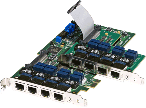
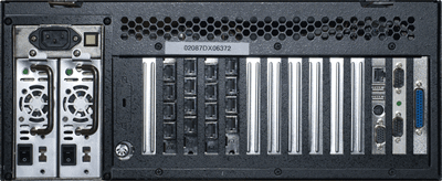
GL's T1 E1 Quad and Octal Cards provide multiple ports for analyzing and emulating TDM networks. Multiple of these PCIe cards can be placed in a single server grade PC for enhanced scalability
Request a Demo / Quote BrochureOverview
Comprehensively emulate and analyze voice, data, fax, analog and digital signals, including echo and Voice Quality with GL's Quad and Octal cards. These high performance PCIe cards can send tones and digits, perform bit error rate testing, record and playback traffic over T1 E1 lines and give full visibility into all time slots on all T1 E1 ports. Furthermore, the cards can analyze many common protocols such as ISDN, ATM, HDLC, MTP2, LAPD, SS7, PPP, GSM, GSM Abis, TRAU, and Frame Relay. The Quad and Octal Cards can also emulate these protocols and generate traffic onto the T1 E1 networks. Multiple Quad and Octal cards can be placed in a single server grade PC and controlled from the same software application. This provides the user the ability to monitor many T1 E1 lines and hundreds of DS0s carrying voice and data.
Features
- Software Selectable T1 or E1 interfacing along with Drop and Insert
- PCI Express x1 Lane/Board
- Monitor the T1 E1 line conditions such as frame errors, violations, alarms, frequency, power level, and clock (or frame/bit) slips.
- TDM, ISDN, SS7 – High Density Voice
- Physical layer analysis includes ability to send alarms and errors via SNMP Traps
- All protocol analyzers now include frame length in protocol statistics selection choice for data link layer
- VoIP, Frame Relay, Multilink Frame Relay, PPP and Multilink PPP, HDLC
- Most all “basic applications” and “special applications” are available for Quad and Octal T1 E1 cards
- Comprehensive Analysis / Emulation of Voice, Data, Fax, Protocol, Analog, and Digital signals, including Echo and Voice Quality testing
- Call Recording, Generation, and Monitoring for hundreds to thousands of calls in one platform
- Windows and Linux Drivers for Open Source Applications
- Media (VoIP) Gateway, IP PBX, and IVR Applications i.e. Asterisk (TM)
- Routing and Bridging emulation over Multi T1 E1 WAN interfaces using MLPPP (Multi Link PPP) and MFR (Multi Link Frame relay) protocols
- Supports “Cross-Port Through” and “Cross-Port Transmit” Modes – these configurations make cabling with Drop/Insert and Fail-Safe Inline Monitoring very easy
- High Density and High Speed – The boards (with Direct Memory Access) are significantly faster and significantly more efficient
- Octal boards are compatible with dual, quad, and higher core motherboards and software that simulate dual and quad cores (hyper-threading)
- Supports both 32-bit and 64-bit Windows® operating system
GL's offers other popular forms of T1 E1 analysis hardware such as
- Dual Express T1 E1 Boards – 2 port PCIe based cards for compatibility with newer motherboards
- tProbe™ T1 E1 Analyzer Unit - an enhanced version of USB based T1 E1 VF & Serial Data analyzer with expansion capabilities
- tScan16 - a high-density T1 E1 board with 16 ports and the newer PCIe (x1) bus interface
Comparison with other PCI based GL's T1 E1 Cards
| Feature | Quad, Octal T1 E1 Boards | Dual T1 E1 Express (PCIe) Boards |
|---|---|---|
| Number of Ports | 4, 8 | 2 |
| PCI Slot Type | PCI Express x1 Bus/ Connector | PCI Express x1 Bus / Connector |
| Speaker (on board) | No speakers | Supported |
| Cross-port and Through Modes | Supported | Supported |
| Pulse Mask Application | Not Supported | Supported |
| Jitter Generation and Measurement | Not Supported | Supported |
| External Clock Mode | No clock port connector | Supported |
| Clock Offset Capability | All ports at the same time | 1 Port at a time |
| VF Interface and Impedance | Not Supported | Supported; 135/150/600/900/High |
| VF Interface for Mic/Headset | Not Supported | Supported |
| Drop and Insert (VF and T1 E1) | No VF connectors; Digital Drop/Insert supported | Supported |
| Onboard RAM | Not Supported | Supported |
Specifications
| Physical Interface | |
|---|---|
T1 E1 Signal |
RJ48c Connectors - Four (4) or Eight (8) per board |
PC Interface |
PCI Express X1 Lane |
| T1 E1 Line Interface | |
|---|---|
Line Code format |
AMI, B8ZS (T1) or HDB3 (E1) |
Framing Formats |
Unframed, D4 (T1), ESF (T1), ESF (J1), CAS (E1), FAS (E1), CCS (E1), CRC4 |
BERT Pattern Generation |
Pseudorandom patterns: (63) 2ˆ6-1, (511) 2ˆ9-1, (2047) 2ˆ11-1, (32767) 2ˆ15-1, (1048575) 2ˆ20-1, (8388607) 2ˆ23-1, QRSS. T1 In-Band Loop Code Generation and Detection, Fixed patterns: All Ones, All Zeros, 1:1, 1:7, 3 in 24. Hardware Compliant: User pattern of up to 32 bits in length International, National & Extra Bits: User Defined (E1) |
Display and Logging |
Bit Errors, Bit Error Rate, Error Seconds, Error Free Seconds, %EFS, Severely Error Seconds, % SES, Degraded Minutes, %Dmin,
Loss Pattern Sync Count, Loss of Sync Seconds, Available Seconds, %Available Seconds, Unavailable Seconds, Bipolar Violations, BPV Rate, BPV Seconds, BPV
Free Seconds, Frame Errors, FE Rate, FE Seconds, FE Free Seconds, with Detailed logging into disk file. |
Drop and Insert |
Any Contiguous set of digital timeslots and/or audio input |
Facility Data Link |
T1 ESF Mode: Transmit/Receive Messages, Bit-Oriented Messages, and files. |
Loopbacks |
Normal (Outward and Inward) |
| Transmit | |
|---|---|
T1 E1 Interface |
Hardware Compliant: |
T1 Output Level |
T1: 3.0V Base to Peak Selectable 0-655Ft Pulse Equalization Setting |
E1 Output Level |
E1: 3.0V ±0.3V Base to Peak |
Line Build-Out Selections |
0dB, -7.5dB, -15dB, -22.5dB for T1 only |
Tx Capability |
DSX-1 Outputs (to 655 feet) |
Alarm Insertion |
Blue, Yellow, Remote, Distant Multiframe, Bit 7 Zero Suppression |
Error Insertion |
BPV, Bit Error, Frame Error, CRC Errors, Burst Frames, Fixed Error Rate, Random Error Rate, auto logic from 10-2 to 10-9 for selectable 56K or 64Kps channels. |
Internal Clock Specification |
Standard: ± 3ppm |
Output Clock Source / Synchronization Options |
Internal, Recovered |
Frequency offset |
OctalE1: +\- 615 Hz |
| Receive | |
|---|---|
Input Impedance |
100 ohms for Terminate and monitor (T1) |
Terminations |
Terminate, Monitor, Bridge |
T1 Input Frequency |
1.544 MHz ± 20 Khz |
E1 Input Frequency |
2.048 Mhz ± 20 KHz |
Frequency Measurement |
± 1ppm |
Error Detection |
Frame Error, CRC Error, CAS Mulitframe Error, BPV Error, Logic Error, Frame Alignment Error
|
Alarm Detection |
D4 Yellow Alarm, ESF Yellow Alarm |
Input Range |
T1:
Monitor
E1:
Monitor
|
Intrinsic Jitter |
Jitter Tolerance: Meets AT&T TR 62411 (Dec. 90)and Meets ITU-T G.823 |
| PCM Interface | |
|---|---|
Transmit |
Synthesized Tone: 15 Hz to 3975 Hz selectable in 1Hz steps, +3.0 dBm to -40 dBm in 0.1 steps selectable, Frequency sweep. |
Receive |
Displays for All Channels: Signaling Bits, Power Level, Frequency, and Data. |
| Miscellaneous | |
|---|---|
Propagation Delay Simulation |
Up to 2 Seconds |
Precision Delay Measurement |
Up to 8 Seconds |
| Physical Dimensions | |
|---|---|
Main Board |
7.7 inches x 4.4 inches |
Daughter Board |
3.8 inches x 4.2 inches |
Hardware Requirement
Available with user-friendly GUI for Windows® 8.1/10 operating systems with support for almost all existing T1 E1 Analyzer applications including Comprehensive Analysis / Emulation of Voice, Data, Protocol, Analog, Digital, and Echo Testing.
* Specifications subject to change without notice.
Loopback
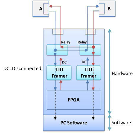
Cross-port Through Loopback
This mode is similar to the standard Outward Loopback except that the signal received on Card 1 (Port 1) is transmitted out onto Card 2 (Port 2). Likewise the signal received on Card 2 (Port 2) is transmitted out onto Card 1 (Port 1). This feature allows monitoring T1 E1 lines in-line while still being protected from loss of power to the board. This mode is effected entirely through relays and eliminates complex cabling.
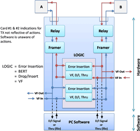
Cross-port Transmit Mode Loopback
In this mode, the data that would normally be transmitted on Card 1 (Port 1) is diverted and transmitted on Card 2 (Port 2) and the data that would normally be transmitted on Card 2 (Port 2) is diverted and transmitted on Card 1 (Port 1). The receive paths are completely unaffected. This mode is particularly useful for Drop and Insert and Error Injection applications in which the board analyzes and may insert traffic running between two pieces of T1 E1 equipment. This feature also eliminates complex cabling.
Resources
Note: PCs which include GL hardware/software require Intel or AMD processors for compliance.
Please Note: The XX in the Item No. refers to the hardware platform, listed at the bottom of the Buyer's Guide, which the software will be running on. Therefore, XX can either be ETA or EEA (Octal/Quad Boards), PTA or PEA (tProbe Units), XUT or XUE (Dual PCIe Express) depending upon the hardware.
| Quick Links |
| T1 E1 Quad/Octal Port Analyzer Brochure |
| Frequency Calibration Procedure User Guide |
| GL Product Lists |
| Presentations |
| T1 E1 Quad/Octal Port Analyzer Presentation |
| Application Notes |
| Backhaul Network Testing Solutions |
| VF Drop and Insert Capabilities |
| Webinars |
 |
 |
