DCME Analyzer
Overview
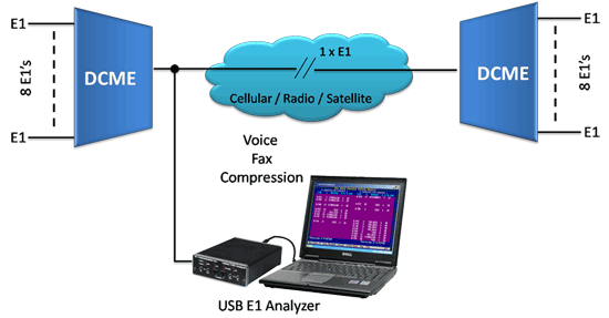
DCME testing, analysis and verification is easy with GL's DCME Analyzer. The DCME Analyzer is a PC-based system (Desktop/Laptop) with GL's Dual port USB E1 pod to connect non-intrusively to the bearer side of DCME equipment. Both real-time and post-processing of the bearer signal is possible. In real-time mode, the status of the bearer including synchronization, bearer loading, fax loading and other statistics are easily monitored.
In post processing mode, the entire DCME bearer signal is captured to the PC's hard disk using the available special E1 applications for recording. The captured file is then analyzed with the DCME software.
In the DCME analysis software, the software aligns to the DCME frame, and the DCME control channel(s) are decoded. The data can be displayed to permit bit level analysis and verification of channel mapping and implementation timing of the DCME protocol. DCMEs use variable bit rate encoding to create overload channels to handle overload conditions. Bearer channels are randomly selected for rate reduction. The software identifies the bit mode of each overload and normal channel (4, 3 or 2 bits).
Additionally, the Facsimile Subframe analysis software permits bit level analysis and verification of fax data submultiplexing on the DCME output bearer signal. The DCME Analyzer software calculates the mapping and interleaving algorithms, FEC and permits time of implementation verification.
Main Features:
- DCME analyzer uses GL's Dual port USB E1 pod to provide the capability to test and analyze DCME signals
- Supports *1IESS-501 Rev 3 Specifications and equipment such as DTX 360 of ECTel
- Connects non-intrusively to the bearer side of DCME equipment
- Captures the entire DCME bearer signal to the PC's hard disk
- Realtime and post processing of the DCME bearer signal
- Verification of channel mapping and implementation timing of the DCME protocol
- Golay and BCH error correction
- Bit level analysis and verification of facsimile data sub-multiplexing on DCME bearer
Note : *1 Although DCME is still used in the Intelsat System, IESS-501 is no longer being updated or distributed since its contents have been subsumed under ITU-T Recommendations G.763 and G.766. Users should, therefore refer to these ITU-T Recommendations for the DCME performance requirements
GL's DCME Test and Analysis Tool Kit
Overview
The latest specification for Digital Circuit Multiplication Equipment (DCME) is IESS-501 (Rev.3), which embodies a complex set of functions including variable rate encoding for voice (32, 24, and 16 Kbps ADPCM), Digital Speech Interpolation (DSI), and voice-band data encoding at 40 Kbps ADPCM. Facsimile demodulation and remodulation is also included. By mid-1994, several vendors started to introduce DCME equipment built to these new specifications.
Compliance with the specification and interoperability between different manufacturers is a key requirement.
GL Communications Inc. has developed a DCME Test and Analysis Tool Kit, comprising a suite of hardware and software to test, analyze and verify critical functions of this new DCME equipment. Key features of this Tool Kit are:
- DCME Test and Analysis System (DTAS) capable of DCME bearer, frame and multiframe, assignment channel, connectivity, bit rotation, audio playback and facsimile control channel analysis
- Dual port USB E1 unit and Application Software for general purpose E1 test and analysis with features such as time, frequency, power, spectral, spectrogram and signaling analysis, together with optional features such as direct to/from disk capability
- Multi E1 Repeater for generation of multiple E1 sources for traffic loading
- Multiplexing and Demultiplexing Software for creation of unique traffic loads for voice, data and fax calls
- Satellite Delay and Precise Error Injection Capability to simulate real conditions and anomalies that stress specific capabilities of DCMEs
Figures 1, 2, and 3 show progressively detailed views of the DCME Test Analysis System (DTAS).
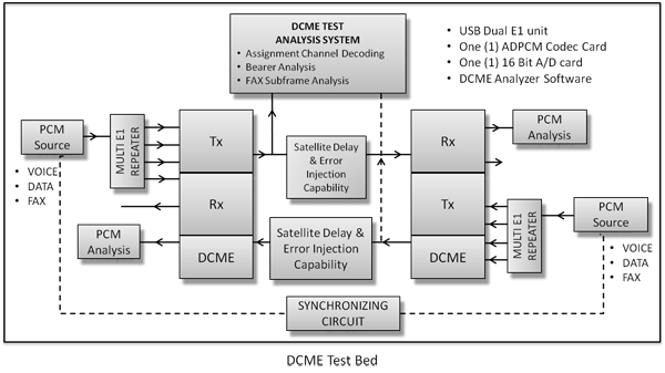
Figure 1: Simplified block diagram depicting hardware and software Test Bed for end-to-end testing of DCMEs
Typical DCME Analysis Configuration
Figure above shows a simplified block diagram depicting hardware and software as a Test Bed for end-to-end testing of DCMEs.
On the trunk sides the DCMEs are loaded with PCM sources consisting of voice, data and fax signals. For some types of signals, such as a fax call, it may be appropriate to synchronize these signal sources. The loaded PCM signals are analyzed after having passed through DCME processing, together with, if required, injected satellite delay and error. The assignment channel, bearer frame and multiframe, connectivities and bit rotation are analyzed using the DCME Test and Analysis System (DTAS). All of the elements shown in Figure 1 are provided by GL. These are:
- PCM source generation is accomplished using GL's Dual port USB E1 unit and accompanying file transfer capability. A PCM file containing voice, voice-band data and fax can be easily generated using GL's multiplexing and demultiplexing software. The software also allows the transmission of synchronized multiplexed files from both ends
- PCM analysis is performed on the data received from the DCME using GL's Ultra E1 Card and application software such as frequency, power, spectral and oscilloscope views. GL can provide voice, voice-band data and fax source files to be used for multiplexing
- Channel loading is accomplished by repeating the single E1 signal generated as described above by GL's Multi E1 Repeater. This device repeats a single input E1 signal into as many as 10 E1 outputs, more than sufficient to load typical DCMEs.
- Satellite delay and error injection is accomplished by utilizing the special application software included with the Dual port USB E1 unit
- DCME bearer analysis is accomplished with specialized software developed for DCME testing, called the DCME Test Analysis System (DTAS). This capability is discussed in greater depth below
This configuration allows both end to end testing and validation of different manufacturer's models of DCME.
DCME Test Analysis System ( DTAS )
System Components
The DTAS connects non-intrusively to the bearer side of the DCME. The DTAS, as shown in Figure 2, consists of:
- A PC based system (Desktop/Laptop) augmented with specific hardware units and DCME specific software as identified below
- Dual port USB E1 unit - capable of interfacing to and analyzing 2.048 Mbps (CEPT) signals
- One 16 bit A/D Card w/ Speakers - capable of audio output
- DCME Test Analysis Software - capable of bearer and fax subframe analysis
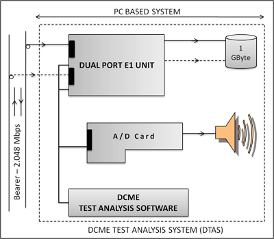
Figure 2: DCME Test Analysis System (DTAS)
DTAS Software Flow
The DTAS software processing flow as shown in Figure 3.
This processing flow is as follows:
DCME Bearer Capture
The DCME bearer signal is captured directly to the PC's hard disk, utilizing the software within the Dual port USB E1 unit. Sufficient hard disk capacity is provided to capture a 2.048 Mbps signal for several days. Typically, about two to three minutes of data are captured - the length of a telephone call.
Bearer File Analysis
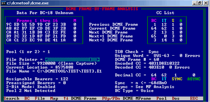
The captured file is then analyzed. Initially the software aligns to the DCME frame and then decodes the DCME control channel(s). The data can be displayed to permit bit level analysis and verification of channel mapping and implementation timing of the DCME. Specific functions are:
- Synchronization to the DCME frame and multiframe by searching for the unique words; this process is performed or verified for every frame and multiframe, i.e unique word detection using thresholds and verification of unique words in frame 0 and frames 1 through 63
- Assembly of the control channel messages
- Decoding and verification of the specified control channel error correction coding (Golay-24,12)
- Decoding and verification of BC and IT identification words
- Decoding and verification of the synchronous and asynchronous data words embedded in the assignment message
- Automatic analysis of the bearer to determine used and unused bearers, number of pools
- Multiframe by multiframe analysis for alarm and backward channel analysis
- Extraction and display of raw bearer data
- Frame by frame DCME map connectivity display
- Utilities for search and analysis of anomalies
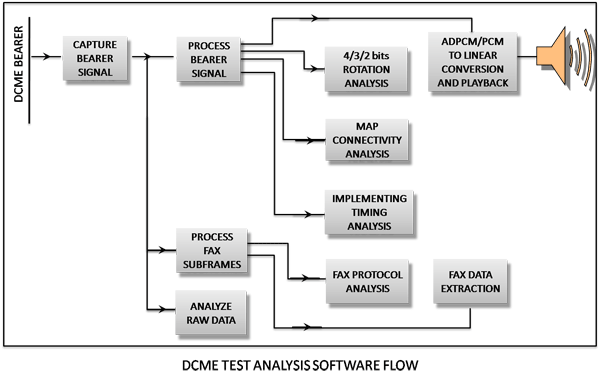
Figure-3: DCME Test Analysis Software Flow
Overload Bit Rotation Analysis
DCMEs utilize digital speech interpolation to provide additional channels. High speech activity, voiceband data and unrestricted 64 kbps channels can produce temporary overload conditions. DCMEs use variable bit rate encoding to create overload channels to handle this excess. Bearer channels are randomly selected for rate reduction. The software identifies the bit mode of each overload and normal channels (4, 3, or 2 bits). Specific functions are:
- Utilities for search and analysis of anomalies
- Create and maintain DCME connectivity maps for the following types of BCs: 64 kbps, 40 kbps, bit bank, fax bank, normal range, 4/3 bit overload, 3/2 bit overload, and pre-assigned
- Verification of connectivity and implementation delay
- Identification of 4/3 bit and 3/2 bit overload channels when assignment messages are generated
- For each selected IT (overload or normal), extraction of the ADPCM words (whether 2, 3 or 4 bit) and decoding to PCM for comparison with the original PCM input
- Audio playback of PCM for analysis
Facsimile Subframe Analysis
In the Rev. 3 DCME specification, fax traffic is demodulated and carried in a complex sub-frame structure that has its own control channels and carries multiple rate facsimile calls, with and without FEC encoding. The Facsimile Subframe Analysis software permits bit level analysis and verification of fax data sub-multiplexing on the DCME output bearer signal. The software implements the mapping and interleaving algorithms, FEC and permits time of implementation verification. Specific software functions are:
- Audio playback of PCM for analysis
- Identification of fax banks and subsequent de-interleaving of facsimile blocks from pre-recorded primary multiplex data
- Verification of facsimile control channel and data block error correction encoding (FEC checking)
- Recomposition of facsimile blocks into facsimile module frame
- Decoding of facsimile control channel (into IT and Message Field)
- Reassembly of facsimile data channels
- Analysis of implementation timing
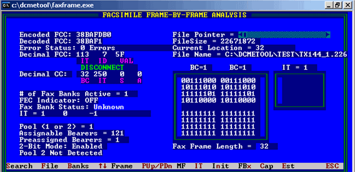
Screen Shot of Facsimile Frame by Frame Analysis
Full Duplex Facsimile Protocol Analysis
Facsimile signals into the DCME are demodulated and transmitted to the remote DCME. Re-modulation of the facsimile signals is performed by the remote DCME. Since a facsimile call involves control and data in both directions, full duplex facsimile protocol analysis has been included. Features of this application are:
- Capture of the timeslots (in both directions) containing the assignment channel and the facsimile control channel.
- Time stamped display of the FCC contents in both directions. The FCC messages can be filtered for specific ITs, active ITs, or all IT messages. A complete facsimile call can be completely analyzed using this feature
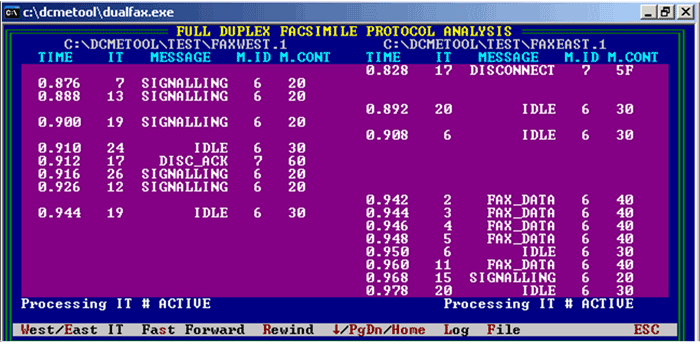
Screen Shot of Full Duplex Facsimile Protocol Analysis
Real-time Bearer Analysis
The DCME bearer signal is captured and processed in real-time. Specific software functions are:
- Real-time IT filtering of the Facsimile Control Channel
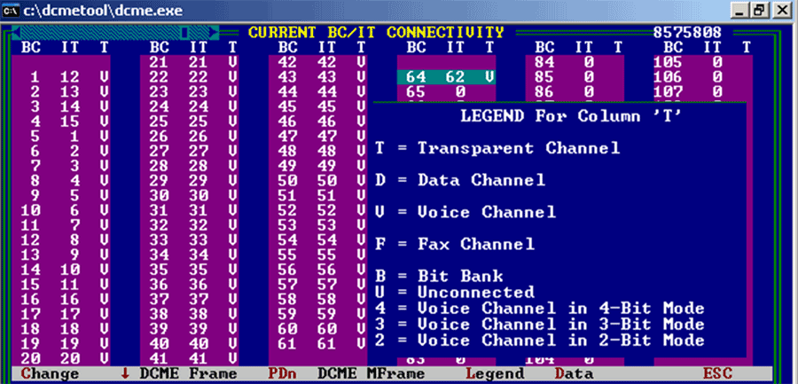
- Real-time display of BC-IT connectivity maps, with implementation of Overload Bit Rotation Analysis
- Real-time display of statistics from the captured DCME bearer signal (i.e. Bearer Status & Format, DCME Sync status, Control Channel status, Facsimile Control Channel status, channel types, etc.)
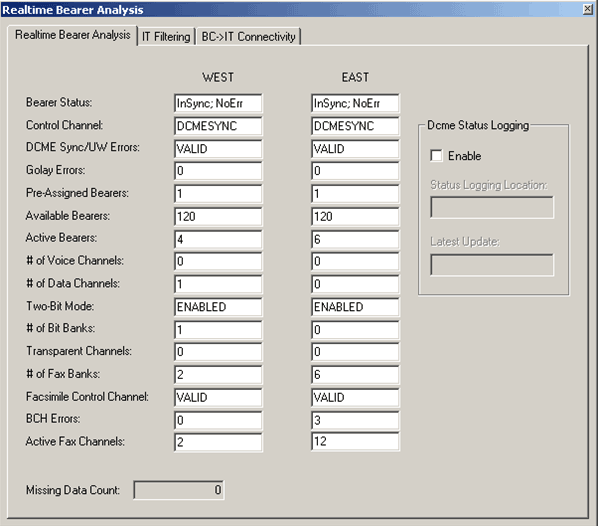
Screen Shot of Real-time Bearer Analysis
ADPCM File Extraction and Conversion
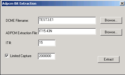
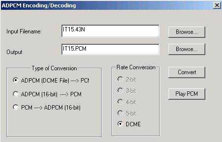
This application allows extracting a voice file from captured data for later playback. ADPCM encoded speech that may be varying in word length (2-bit, 3-bit, and 4-bit mode) and assigned or unassigned a bearer is extracted from the captured file and appropriately tagged for later conversion to PCM. The IT may be assigned to a normal or overload bearer channel and may be "jumping bearer channels during bearer connections and disconnections.
Resources
Note: PCs which include GL hardware/software require Intel or AMD processors for compliance.
| DC007 - DCME Test and Analysis Software (with a Desktop PC): | DC008 - DCME Test and Analysis Software (with a Portable PC): |
|---|---|
| Includes: Minimum Specifications | Includes: Minimum Specifications |
| Dual port USB E1 pod | Dual Port USB E1 Pod |
| Desktop PC (latest model) | Notebook PC (latest model) |
| Brochures |
| DCME Analyzer Brochure |
| GL Product Lists |
| Presentations |
| DCME Analyzer Presentation |
 Back to Protocol Analysis Index Page