ATM IMA Emulator
Overview
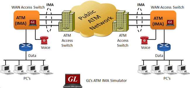
The Inverse Multiplexing over ATM (IMA) Emulator application can simulate the inverse multiplexing of an ATM cell stream over multiple physical links and retrieve the original stream at the far-end from these physical links. The multiplexing of the ATM cell stream is performed on a cell by cell basis across the multiple physical links. Traffic source can be sequence number, HDL files (containing packets/frames), flat binary file, user-defined frames (ASCII HEX file), and Ethernet data.
The ATM Inverse Multiplexing technique involves inverse multiplexing and de-multiplexing of ATM cells in a cyclical fashion among links grouped to form a higher bandwidth logical link whose rate is approximately the sum of the link rates. This technique provides an effective method of combining the transport bandwidths of multiple links (e.g., DS1/E1 links) grouped to collectively provide higher intermediate rates. This is referred to as an IMA grouping.
Along with AAL0 and AAL5 IMA supports AAL2 which provides bandwidth-efficient transmission of low-rate, short and variable length packets in delay sensitive applications. AAL2 also provides for variable payload within cells and across cells by using segmentation and reassembly technique. AAL type 2 is subdivided into the Common Part Sublayer (CPS) and the Service Specific Convergence Sublayer (SSCS).
GL's IMA Emulator is available as optional client-server based application with GL's T1 E1 Analysis hardware. GL also offers ATM analysis application for real-time capture and analysis of ATM IMA cells over T1 E1 lines. Please visit ATM Protocol Analyzer page for more details.
Main Features:
- Performs IMA simulation on up to 16 T1 E1 ports
- ATM links can be created on full or fractional timeslots
- Supports hyper channels with discontinuous (sparse) timeslots
- IMA Frame Length can be set equal to 32, 64, 128, or 256
- Dynamically add/remove (Open/Close) of ATM links without loss in data
- Multiple IMA groups can be created with each group configured with multiple virtual channels for traffic tx/rx
- Generate and verify end to end traffic on each Virtual Channel
- User configurable ATM (AAL 5, AAL 2) Packet size
- Payload traffic generation and verification using Sequence number, HDL file (containing packets/frames), Flat Binary file, and User defined frame (ASCII HEX file) for each Virtual Channel independently
- Transmit and receive Ethernet traffic over T1 E1 links by operating in bridge mode
- Provides detailed statistics for all IMA groups and each Virtual Channel associated with a group
- Provides end to end traffic verification statistics
- Ideal solution for automated testing using command line scripts
Simulating ATM Inverse Multiplex Groups and Links
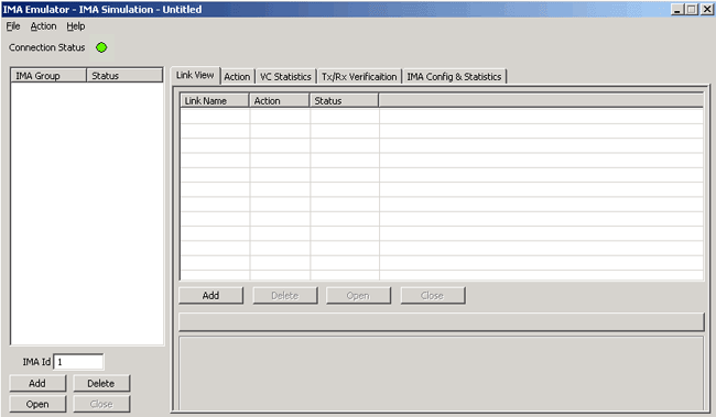
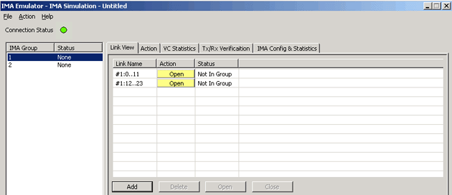
The IMA Emulator allows grouping multiple link-layer channels into a single network-layer channel. An IMA group can consist of multiple physical links of the same type. Data sent through this channel will be distributed among all the links. It is a technique used to derive larger bandwidth pipe by aggregating smaller bandwidth pipes e.g. from multiple T1s or E1s. Each IMA group can be configured with IMA Frame Length (equal to 32, 64, or 256) and Group Symmetry modes. Users are also allowed to create/delete Virtual Channels to generate/receive traffic on the created virtual channels.Various links (of any bandwidth varying from 64Kbps to n*64Kpbs or sub channels) can be added in IMA Simulation. Two or more than two timeslots can be grouped to constitute a Hyper-channel with discontinuous (sparse) timeslots
Traffic Generation and Verification
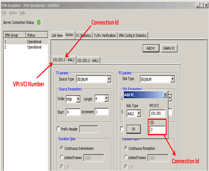
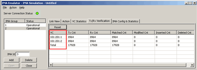
GUI provides options to add virtual channels to IMA groups to perform traffic generation and verification. Tx parameters are used to generate the ATM traffic and Rx parameters are used as reference to verify the received frames. The results of the verification are displayed in Tx/Rx Verification tab. The parameters for each VC are independently set.
The IMA permits transmission and reception of following source/sink types:
- Sequence numbers (1,2,4 or 8 least significant byte first (LSB) or most significant byte first (MSB)) with configurable start sequence numbers and increments
- User defined HEX string frame, which is ASCII based. Can be edited, loaded and saved
- Binary flat files that allows user to provide any random data
- GL *.HDL trace file is GL's packet file format which can be constructed pre-hand or captured using ATM Analyzer
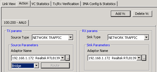
- Network traffic (LAN traffic) - This allows user to receive traffic from Ethernet, convert to ATM traffic and send through T1 E1 line and vice versa. IMA emulator can be configured in bridge mode to establish connection and route traffic between LANs. Priority is set based on source IP address, destination IP address, length, or type of service of the packets received from the Ethernet
Other parameters that can be customized include
- Prefix Header - allows the user to prefix a header at the beginning of the ATM packet to be transmitted
- Duration Spec - defines the duration for which Tx/Rx will be done
- Payload length - defines the ATM packet size. Each link can have its own payload size
- Max CPS length - defines the payload length for CPS(Common Part Sublayer) packet
IMA Emulator as a Bridge
When the emulator is configured to act as bridge between two networks, all traffic received from the network is encapsulated into AAL5 and the ATM cells are streamed over T1 E1 links. The Emulator on another network removes ATM header, converts to Ethernet and streams to the destination.
Data Verification using Statistics
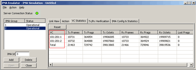
Group Statistics will show statistics of transmitted frames, received frames, transmitted octets, and received octets for the selected IMA group.
It shows the VC statistics for each of the added VCs of the selected IMA group. The statistics include: number of Transmitted and received frames, Fragments, Octets, and Lost fragments.
Traffic verification results provide the overall statistics for all VCs. The statistics include number of VCs created, Transmitted, Received, Matched, Modified, Inserted and Deleted frames.
Using Command Line
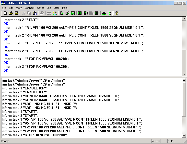
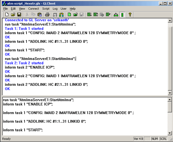
All the actions performed in GUI can also be executed through command line interface.
Creating IMA Bundles
Syntax: inform task num "[CONFIG: [IMAID num] [IMAFRAMELEN num] [SYMMETRYMODE num]]";
This command is used to configure the IMA Group with user selectable IMA Group ID and IMA frame length and mode of Transmission.
Adding Links to the Group
Syntax: inform task * "ADDLINK: [HC #num]:[Bandwidth] [LINKID num]";
This command will add links to the selected group. Each task is added as one IMA Group and to that Group we can add links with this command and the link can be Hyper Channel or Single TS or Sub channel
Traffic Generation and Verification on Virtual Channels
Syntax: inform task num "[[Tx:/Rx:] [VPI num] [VCI num][AALTYPE num][durationSpec] [typeSpec][FIXLEN num][SKIPBYTES num][REV_BIT] [PREFHED num]";
This command starts the Tx /Rx task on IMA bundles. Specify the VC on which traffic to be transmitted or received and also, specify duration (Limited Tx, Continuous, EOF), source data (SEQNUM, HEXSTR, HDLFILE, BINFILE), payload length for IMA Group links. On a Group we can create required number of VC and each VC can carry different types of traffic like Sequence Numbers, Hexadecimal Traffic, or offline file in the format of HDL, or data as a payload.
To download sample script that illustrates the transmission and reception of traffic in IMA simulation using Sequence numbers.
To download sample script that illustrates the transmission and reception of traffic in IMA simulation using HDL Trace Files.
Resources:
Please Note: The XX in the Item No. refers to the hardware platform, listed at the bottom of the Buyer's Guide, which the software will be running on. Therefore, XX can either be ETA or EEA (Octal/Quad Boards), PTA or PEA (tProbe Units), depending upon the hardware.
| Item No. | Item Description |
| XX654 | Inverse Multiplexing over ATM Protocol Emulator |
| Related Software | |
| XX160 | T1 or E1 ATM Analyzer |
| XX135 | T1 or E1 MLPPP Analyzer |
| XX636 | MC-MLPPP Emulation and Analysis |
| XX130 | T1 or E1 Real-Time Frame Relay Protocol Analyzer |
| XX655 | MultiLink Frame Relay Emulation w/ Tx/Rx Test (requires XX600 & XX634) |
| Related Hardware | |
| PTE001 | tProbe™ Dual T1 E1 Laptop Analyzer with Basic Analyzer Software |
| XTE001 | Dual T1 E1 Express (PCIe) Boards (requires additional licenses) |
| FTE001 | QuadXpress T1 E1 Main Board (Quad Port– requires additional licenses) |
| ETE001 | OctalXpress T1 E1 Main Board plus Daughter Board (Octal Port– requires additional licenses) |
| Brochure/Presentation |
| T1 E1 Client Server IMA Brochure |
| ATM Overview Presentation |

 Back to Client/Server Scripted Control Software Page