MAPS™ CAS Protocol Emulator
MAPS™ CAS Emulator supports typical CAS signaling methods including Loop Start, R1, MFC-R2, SS5, Sweden P7, FGD, and other variants of these methods.
Request a Demo / Quote Brochure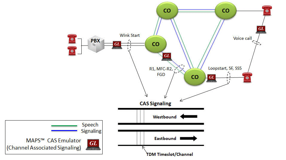
Background
Signaling that occurs between switches (such as PBXs, local exchange carrier and interexchange carrier) in telephone networks is sent either within the voice traffic or on a separate dedicated signaling channel. Channel Associated Signaling (CAS) is a method of signaling where a channel or timeslot carrying speech also carries with it the signaling and addressing to set up and tear down calls. This supervisory signaling carried as "on-hook" and "off-hook". The addressing is carried as DTMF (Dual Tone Multi Frequency) or as MF (Multi Frequency). This form of signaling is still used to route calls on the public switched telephone network (PSTN) including subscriber lines like 2wire local loops, on trunks between central offices (CO), and on access trunks such as PBXs. Typical CAS signaling methods are: Loop Start, R1, MFC-R2, SS5, Sweden P7, FGD, SF Signaling, Voice Call and other variants of these methods.
In the T1 world, CAS protocols are implemented through "robbed bit signaling", a unique way of signaling that has always caused confusion among engineers. In the E1 world, CAS protocols are implemented through time-shared use of timeslot 16. In both systems, dual tones representing digits are used for ANI and DID identifiers.Overview
CAS emulation is added to GL's Message Automation and Protocol Simulation (MAPS™) platform. MAPS™ is a protocol simulation and conformance test tool that supports a variety of protocols such as SIP, MEGACO, MGCP, SS7, ISDN, GSM, MAP, CAS, LTE, UMTS, SS7 SIGTRAN, ISDN SIGTRAN, SIP I, GSM AoIP, Diameter and many others.
MAPS™ CAS Emulator is a client-side application that works along with GL’s T1/E1 Analyzer Cards and Windows Client/Server software. This test tool is used to perform testing using CAS signaling and transmission and detection of TDM traffic over T1/E1 using scripts, and offers a complete solution for testing, troubleshooting, and maintenance of devices and networks implementing CAS. MAPS™ CAS automates the testing procedure with ready scripts for inbound and outbound calls. Calls are established, once the signaling information such as signaling bits, DTMF/MF digits, or Tones are sent or detected.
MAPS™ CAS is widely used for following test solutions-
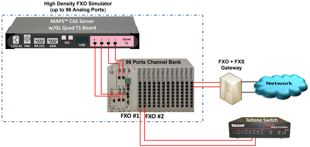
- High density FXO Simulation - supports up to 96 Analog Channels
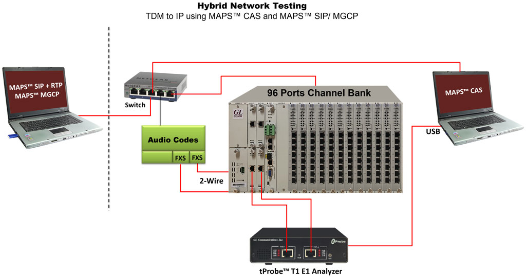
(using MAPS™ CAS and Channel Bank) - Testing Hybrid networks - using MAPS™ CAS and MAPS™ SIP/MGCP
(using MAPS™ CAS, Channel Bank, and MAPS™ SIP/MGCP)
GL’s MAPS™ CAS Emulator requires additional licenses:
- XX610 - Client Server w/Tx-Rx File
- XX620 - Client Server w/Dtmf
- XX630 - Client Server w/Dsp
- Channel Bank (APSCB-24 or APSCB-48) for 2wire emulation
- XXXFT0 - Fax emulation option
MAPS™ CAS Emulator supports typical CAS signaling methods including Loop Start, R1, MFC-R2, SS5, Sweden P7, FGD, and other variants of these methods. MAPS™ CAS also supports simulation of SF, Voice Call and SS5 Signaling using VF Input/Output interfaces available on tProbe hardware unit.MAPS™ CAS includes powerful utilities like Profile Editor and Script Editor which allow new scenarios to be created or existing scenarios to be modified for CAS Signaling. The test configuration window allows users to configure various CAS signaling types (Loop Start, R1, MFC-R2, SS5, Sweden P7, FGD, SF Signaling, Voice Call) including R1 digit parameters, flow control parameters, forward/ backward tone parameters and various others to transmit and receive CAS inbound and outbound signals.
MAPS™ CAS supports simulation of CAMA trunks connected to the 911 selective router (SR). CAMA type signaling trunks are used to provide the calling party’s Automatic Number Identification (ANI) to the selective router. The selective router then routes the call to the appropriate Public Safety Answering Point (PSAP) based on the calling party’s location. Both analog and digital (T1) CAMA simulations are supported. Analog simulation requires an additional channel bank specially configured for CAMA.
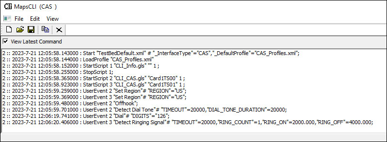
MAPS™ application supports a Command Line Interface (CLI) such as the Python and Java scripting tools, to provide the capability of remote operation, automation, and multi-site connectivity.
With the purchase of additional licenses (xx610, xx620, xxFT0) traffic can be simulated over T1/E1 interfaces. Supported traffic includes transmission and detection of TDM digits, voice files, single tone, dual tone, speech and FAX. Also supports various traffic events simulation during the course of a call.
Features
Call Scenarios |
|
Protocols |
|
Functionalities |
|
Solutions |
|
CLI Capabilities |
|
Reporting |
|
Solutions
| Solution 1: High Density FXO Simulation with MAPS™ CAS and Channel Bank | |||||||||||||
MAPS™ CAS Solution |
|
||||||||||||
| Solution 2: End-to-end Hybrid Network Testing using High Density MAPS™ CAS and Channel Bank | |||||||||||||
 |
|
||||||||||||
Supported Protocols Standards
MAPS™ CAS Simulator supports the following CAS protocols:
- E1 MFC-R2 Signaling - Defined by the ITU Recommendations Q.421-Q.442, uses a multi-frequency compelled signaling protocol to exchange address information. Sends MFC-R2 forward and backward tones per CCITT specifications. MAPS CAS includes ready profiles for India, China, Mexico and different country specific implementations will be supported in future.
- E1 European Digital CAS (EUC)
- E1 Digital E & M
- E1 International Wink Start
- E1 Sweden P7
- T1 Wink Start (R1 wink) - The R1 wink protocol uses one-bit signaling, and the wink (brief presence of current or variation of the signaling bit) that the inbound side uses to indicate readiness to receive address signaling
- T1 Loop Start
- T1 Ground Start
- T1 Feature Group D
- T1 Immediate Start
- T1 FXO CAMA (Centralized Automated Message Accounting)
- T1 SF Signaling
- T1 Voice Call Signaling
- T1/E1 SS5 Signaling
- Any User-Defined CAS Protocol
E1 MFC-R2 Call Simulation
The following table describes the line signaling for a typical call:
| State | Outbound (AfBfCfDf) |
Direction | Inbound (AbBbCbDb) |
| Idle | 1001 (Idle) |
------- <------- |
1001 (Idle) |
| Seizure | 0001 (State=INIT) |
-------> | Seizure Detected Incoming Call |
| Seizure acknowledged | <------- | 1101 State=Idle |
|
The outbound sends the address information using in-band compelled MF tones. The inbound completes the compelled sequence by accepting or rejecting the call, using the last backward compelled tone. If the call is accepted, the inbound plays a ring tone on the line, and then signals answer call by setting the Ab bit to 0. |
|||
Ringing |
|
<------- |
Send ring back tone |
Answer - conversation state |
(State=Outbound Initiated) |
<------- |
0101 |
Depending on which side hangs up the call first, a clear back signal or a clear forward signal is generated. Depending on national specifications, there might be a period of time in which the inbound side holds a release guard state, which is the same as clear back but happens when the outbound side is already in the idle state. Idle follows. |
|||
Inbound hangs up first: Clear back |
|
<------- |
1100 |
Clear forward |
1001(call Released) |
-------> |
|
Idle |
1001 |
-------> |
1001 |
Outbound hangs up first: Clear back |
1001 |
-------> |
|
Release guard |
|
<------- |
1100(call Released) |
Idle |
1001 |
-------> |
1001 |
MAPS™ CAS MFC-R2 can place and answer call on the selected timeslot and Send or Receive Traffic. The ready scripts used can detect events and respond with appropriate actions with respect to the states.
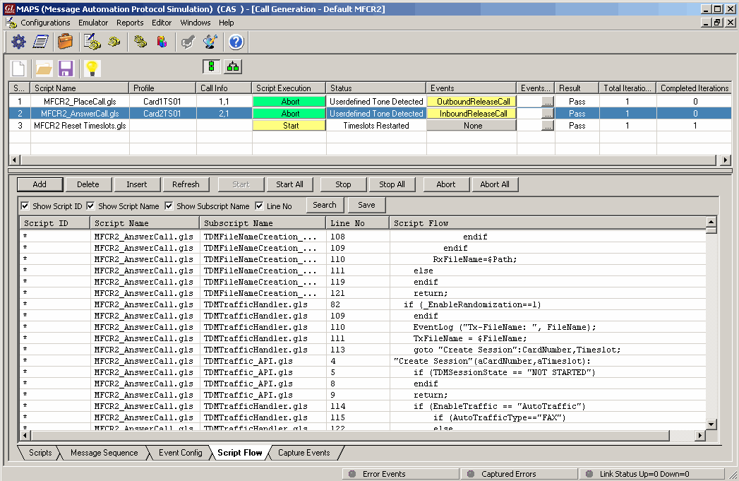
CAS MFCR2 Place and Answer Scripts
The Events encountered during the progress of the calls are logged as seen in the screen below.
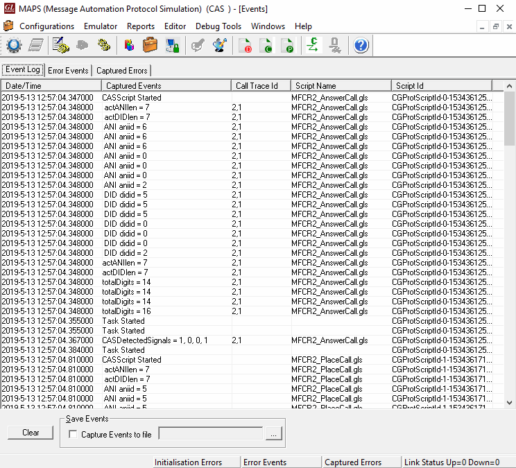
Screenshot of MFCR2 Call Events Log
FGD Call Simulation
The following table describes the line signaling for a typical call:
| State | Outbound AfBf | Direction | Inbound AbBb |
| Idle | 0 0 | <---------------> | 0 0 |
| Seizure | 1 1 | ---------------> | |
| Seizure acknowledged | <--------------- | 1 1 – 0 0 (Wink) | |
The outbound side starts to send the address information using MF tones. Feature group D can transfer more than one digit field to speed up long distance calls. Every field starts with a KP tone (start of pulsing) and ends with ST tone (end of pulsing). After each digits field the inbound side acknowledges the reception with a signaling bit wink. |
|||
| Register signaling first field digit spill | MF tones Start KP |
---------------> | |
| Called Number | ---------------> | ||
| MF tones End ST |
---------------> | ||
| MF tones Start KP |
---------------> | ||
| Calling Number | ---------------> | ||
| MF tones End ST |
---------------> | ||
| Acknowledgment of Digits Reception | <--------------- | 1 1 – 0 0 (Wink) | |
| Once all the address information has been transferred, the inbound side accepts the call by sending the off-hook signaling code or rejects the call sending Idle signaling code If the call is rejected, the outbound side switches back to signaling AB = 00 (idle), clearing the line. |
|||
| Clear forward | 0 0 | <---------------> | 0 0 |
| If the call is accepted, the inbound side answers the call by flipping both backward bits to 1. | |||
| Answer | <--------------- | 1 1 | |
| Call Active - Conversation State | |||
| Clear | 0 0 | <---------------> | 0 0 |
| Idle | 0 0 | <---------------> | 0 0 |
MAPS™ CAS FGD can place and answer call on the selected timeslot and Send or Receive Traffic. The ready scripts used can detect events and respond with appropriate actions with respect to the states.
FGD Place and Answer Scripts
The Events encountered during the progress of the calls are logged as seen in the screen below.
FGD Call Events Log
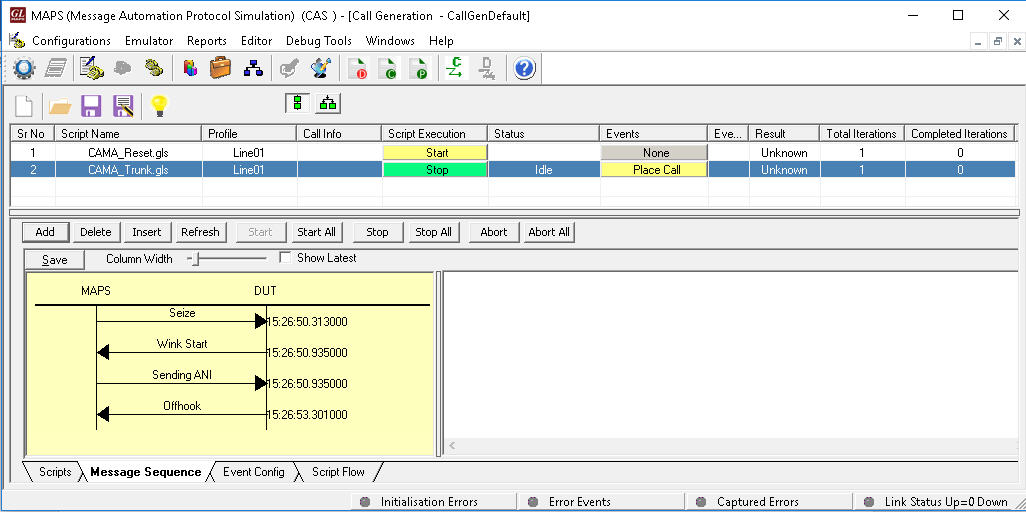
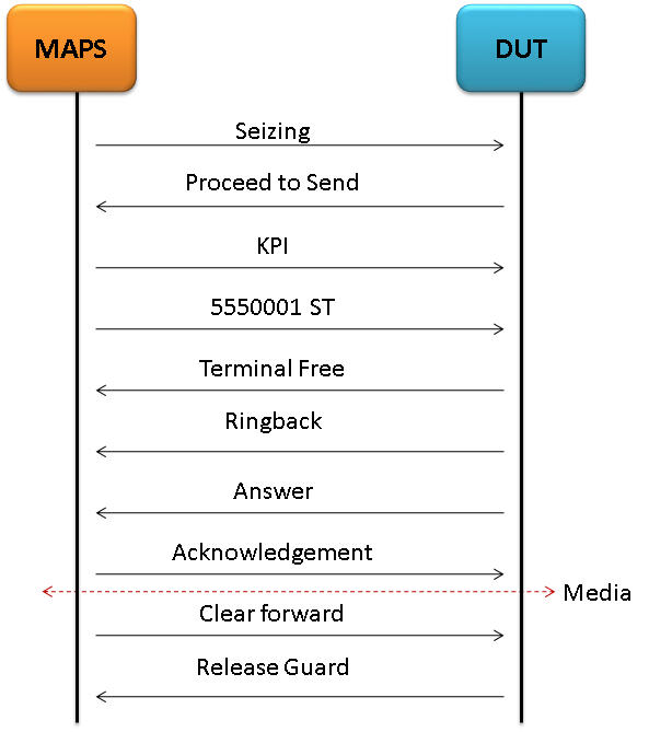
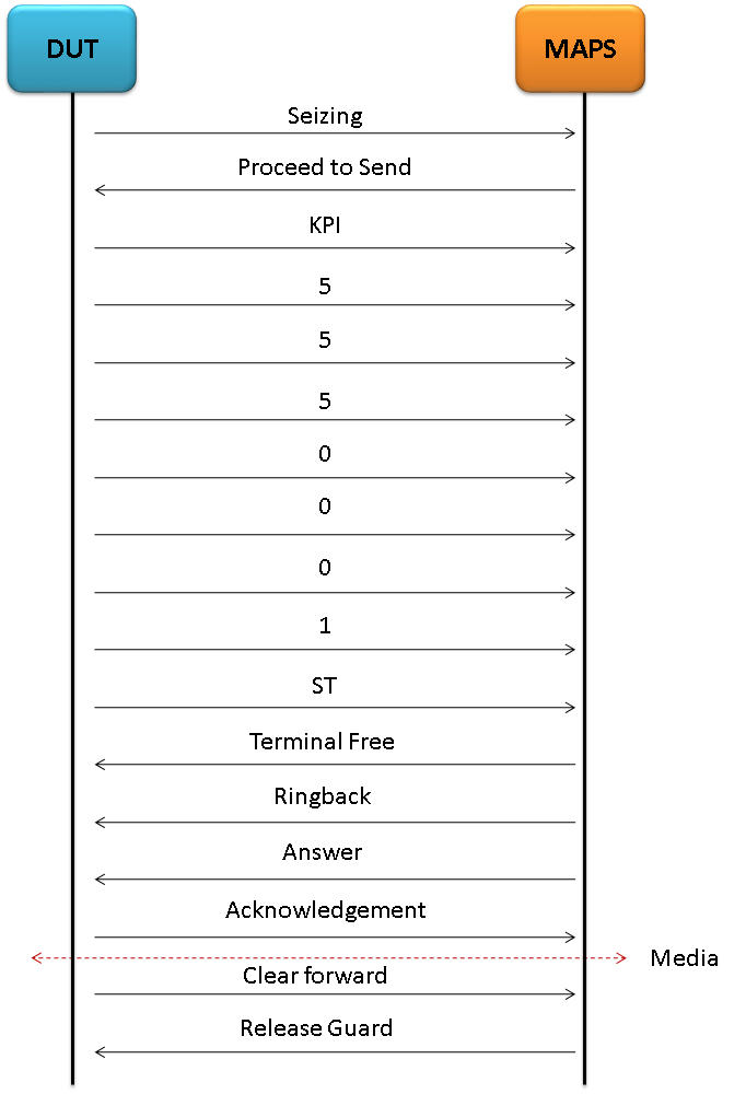
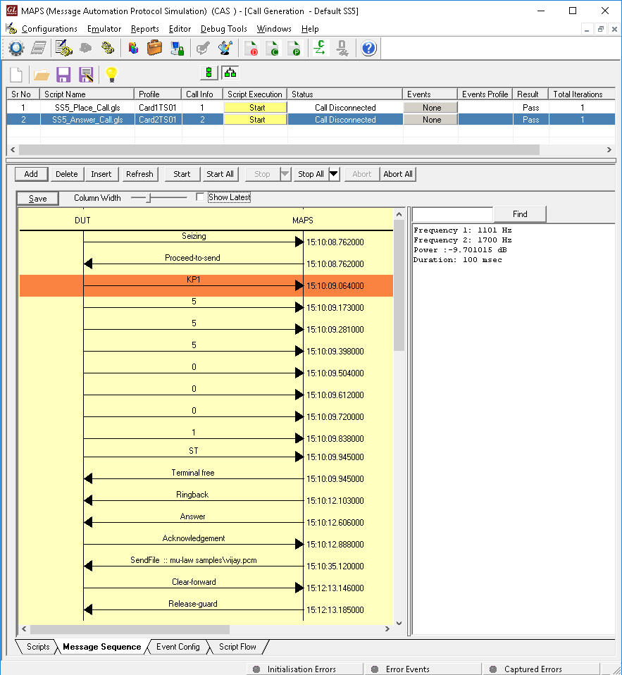
T1 Wink Start (R1 wink) Call Simulation
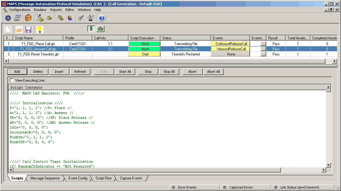
Call Generation feature allows the user to simulate incoming and outgoing communications in CAS network, where signaling transitions occurs between switches, using proper scripts and profiles. The profile allows necessary parameters of call controls to be changed during runtime.
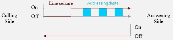
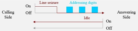
The following depicts the typical CAS signaling procedure for Loop Start lines -
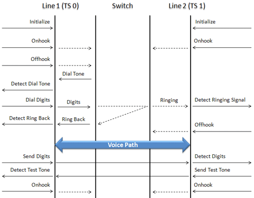
Side A to Side B CAS Call Flow
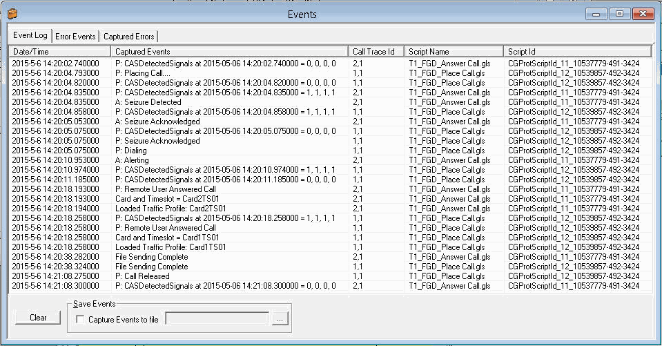
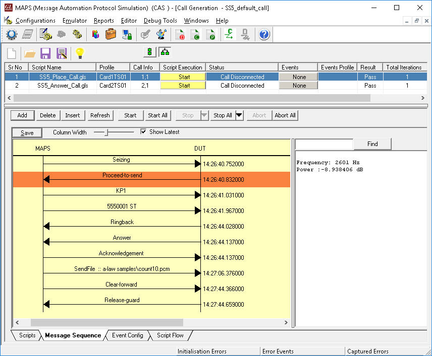
The screenshot below shows MAPS™ acting as outbound terminal and transmitting the signaling bits to the other switch
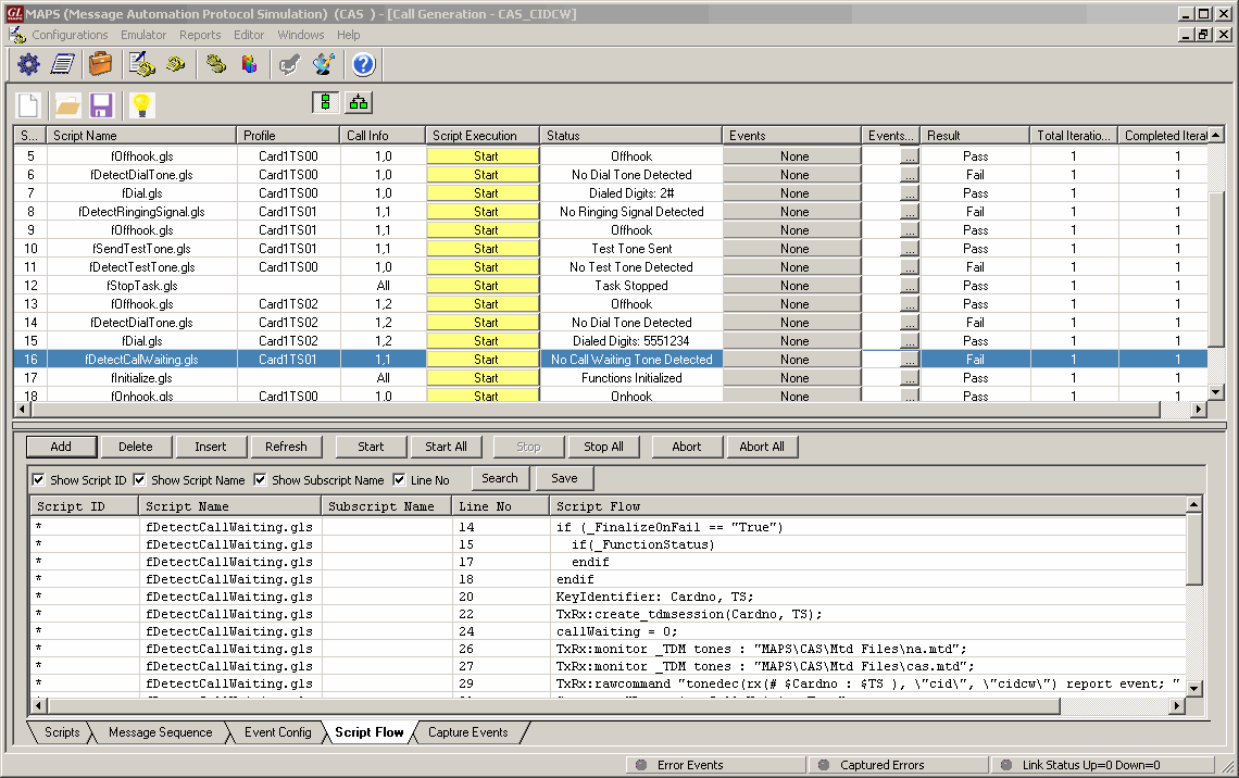
CAS CIDCW – Call ID Call Waiting Script
MAPS™ provides Event Log, Error Events, and Captured Errors report log encountered during the progress of the call.
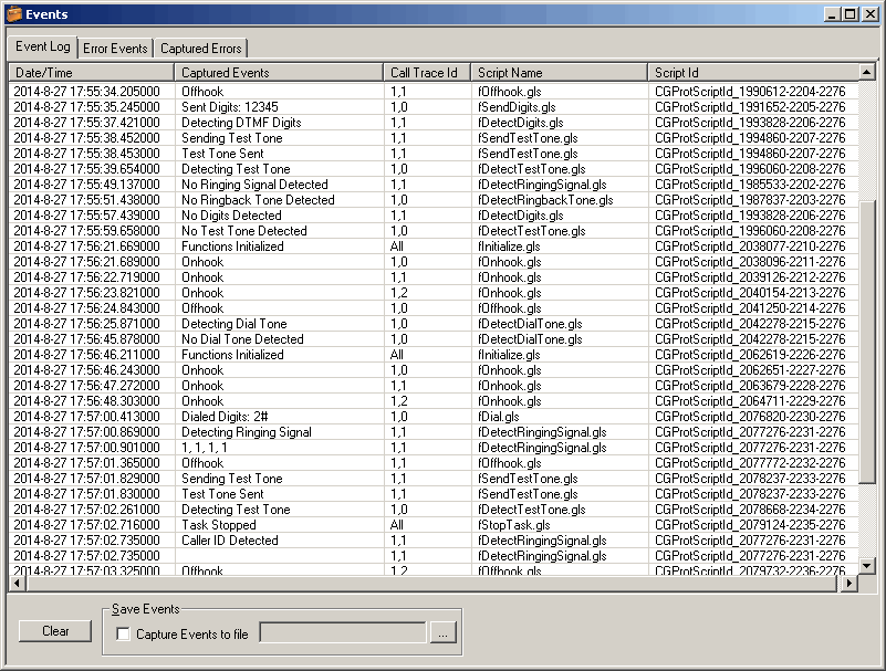
CIDCW Call Events Log
European Sweden P7 Call Simulation
The following table describes the line signaling for a typical call:
CAS Signaling PABX (tProbe™) to Multiplexer (Subscriber)
| Signal or state | ASB 501 a | b | c | d |
Multiplexer a | b | c | d |
| Idle | 1 0 0 1 | 1 0 0 1 |
| Seizure (Ringing) | 1 0 0 1 Line 0 1 0 1 Signal ---------------> |
1 0 0 1 |
| Answer (Off Hook) | Line 0 1 0 1 Signal <--------------- |
1 0 0 1 0 0 0 1 |
| Stop ringing | 0 1 0 1 Line 0 0 0 1 Signal ---------------> |
0 0 0 1 |
| Register recall | Line 0 0 0 1 Signal <--------------- |
0 0 0 1 1 0 0 1 0 0 0 1 |
| Clear backward | tone 1 0 0 1 Signal >>>>>>> |
X 0 0 1 |
| On Hook (clear forward) | Line 1 0 0 1 Signal <--------------- |
0 0 0 1 1 0 0 1 |
MAPS™ CAS SwedenP7 can place and answer call on the selected timeslot and Send or Receive Traffic. The ready scripts used can detect events and respond with appropriate actions with respect to the states.
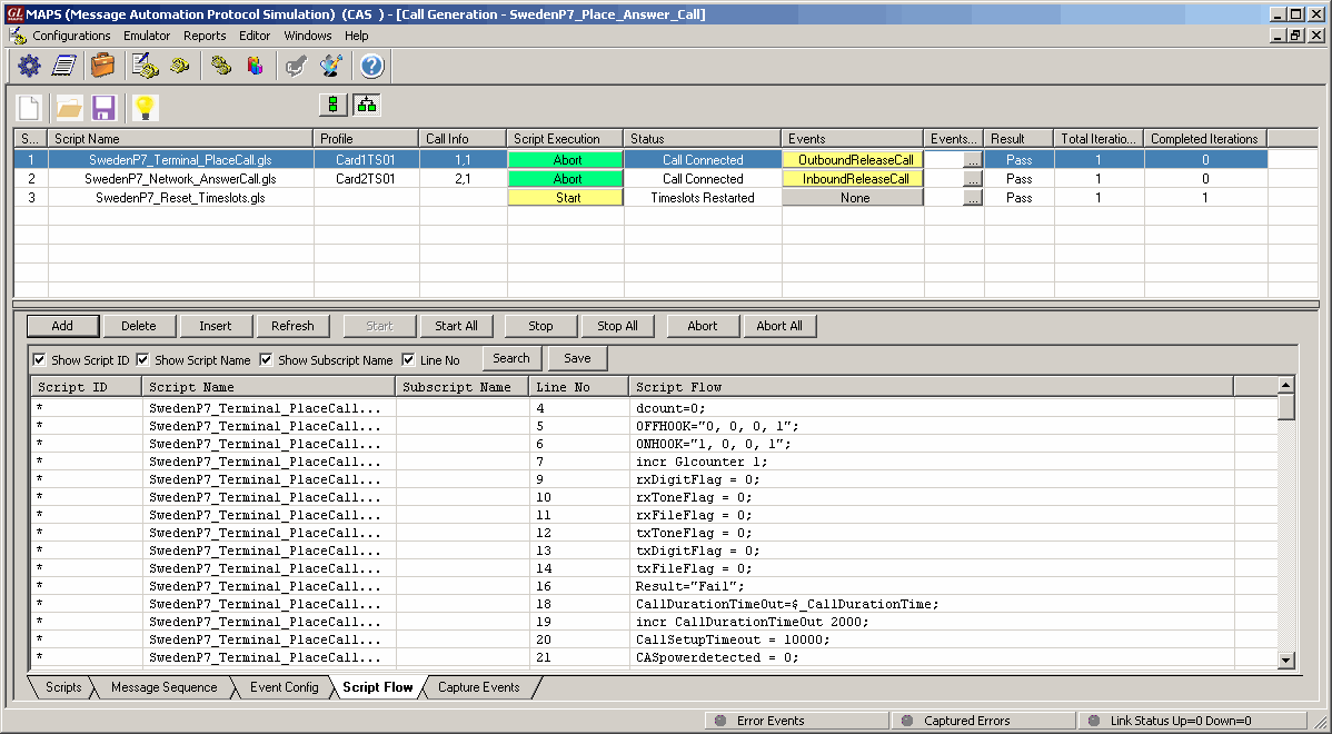
SwedenP7 Place and Answer Scripts
The Events encountered during the progress of the calls are logged as seen in the screen below.
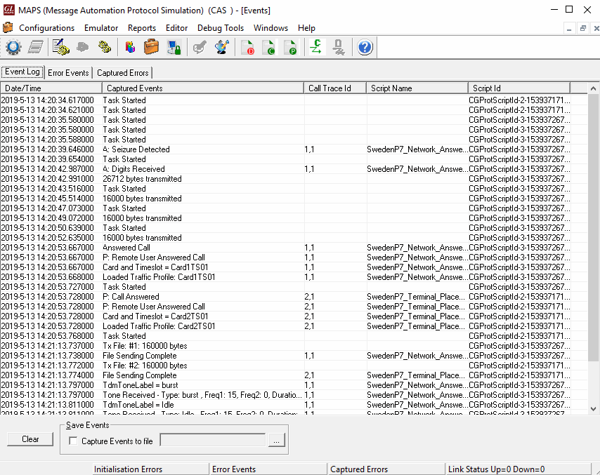
SwedenP7 Call Events Log
CAMA Signaling Simulation for 911 Systems
CAMA is a special analog trunk originally developed for long-distance billing but is now mainly used for emergency call services: 911 and Enhanced 9-1-1 (E-911). CAMA trunk connects a customer switch directly to the selective router (SR) in the service provider network.
GL’s MAPS™ CAS Emulator can be used to simulate CAMA trunks connected to the 911 selective router (SR). CAMA type signaling trunks are used to provide the calling party’s Automatic Number Identification (ANI) to the selective router. The selective router then routes the call to the appropriate Public Safety Answering Point (PSAP) based on the calling party’s location.
Both analog and digital (T1) CAMA simulations are supported. Analog simulation requires an additional channel bank specially configured for CAMA.
The below figure illustrates a typical FXO CAMA signaling scenario where MAPS™ CAS simulates the CAMA trunk connected to the 911 selective router.
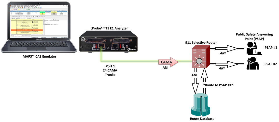
Digital CAMA Simulation
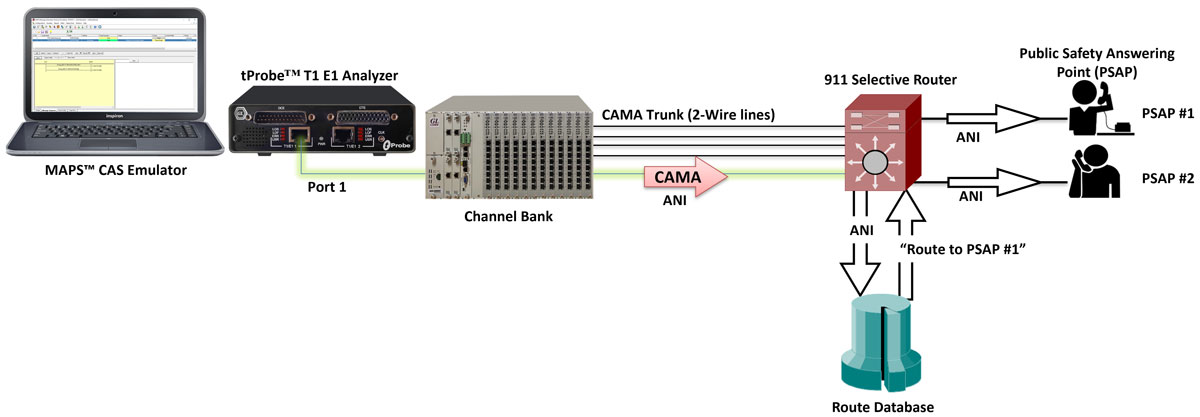
Analog CAMA Simulation
CAMA circuits connected to the E-9-1-1
CAMA type signaling is used for provisioning the calling party’s Automatic Number Identification (ANI) to the 911 selective router.
The ANI in the form of MF digits can be defined as: KP-I-NXX-XXXX-ST, where,
- KP - indicates a KP (Key Pulse) signal
- I - information digit
- NXX - the prefix of the telephone number (exchange)
- XXXX - the caller’s PBX station number
- ST - indicates a ST (Start Pulse)
The figure below outlines the signaling sequence for CAMA type trunks connected to the 9-1-1 switch:
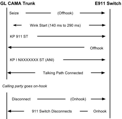
Signaling sequence for CAMA type trunks connected to E-911 switch
CAMA trunks connected to PSAP
For an alternative configuration in Private Exchange Branches (PBX) where the CAMA trunks are connected directly to the PSAP, the ANI is defined as: KP-NPD-NXX-XXXX-ST where,
- KP - indicates a KP (key pulse) signal
- NPD - numbering plan digit representing the area code of the PBX caller who originated the 9-1-1 call
- NXX - the prefix of the telephone number (exchange)
- XXXX - the caller’s PBX station number
- ST - indicates a SP (Start Pulse)
The figure below outlines the signaling sequence for CAMA type trunks connected directly to the PSAP:
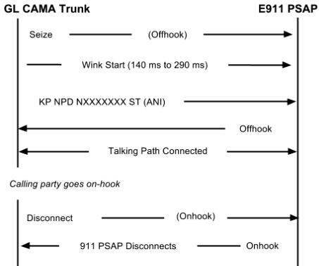
Signaling sequence for CAMA type trunks connected to the PSAP
MAPS™ CAS Emulator application displaying a real-time signaling sequence of the CAMA type trunk connected to the 911 selective router.
MAPS™ CAS simulating CAMA trunks
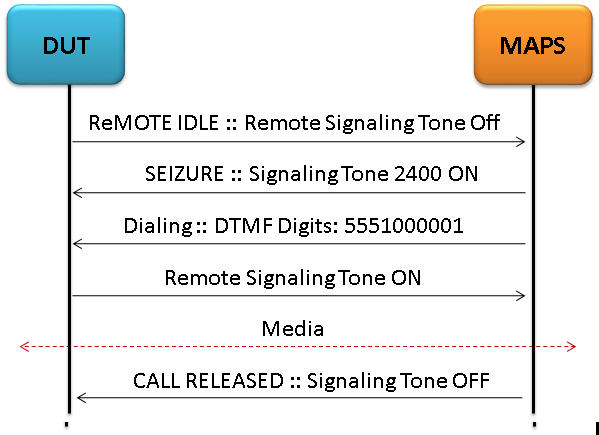
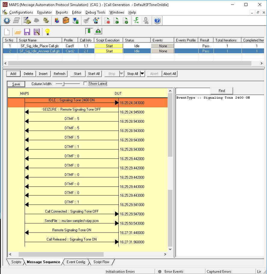
Single Frequency (SF) Signaling
In analog circuits, channel bandwidth is divided into a 300 – 3400 Hz “voiceband” used for speech and/or data, and a “supervisory band” centered at 2400/2600/2800 Hz used for the signaling tone. Because both the supervisory signal (SF Tone on Idle and Active modes) and line traffic are carried in the same channel, filters are normally required at each end of the connection to separate out the line signal from the voiceband traffic.
MAPS™ CAS Single Frequency (SF) simulator can generate signaling tone on Idle and Active Modes with configurable operational frequency (2400/2600/2800 Hz) bands for analog G/G interface. It also has efficient filters to extract Voice from line signals and filters to inform the state of the remote-end efficiently.
Other related features include -
- Selection to SF signaling on Idle and Active mode operation
- User configurable Signaling Tone
- User control on call to Terminate, Answer, Reject calls
- Extracted voice can be recorded
- Ladder diagram for call flows
- Events window to keep track of the call status
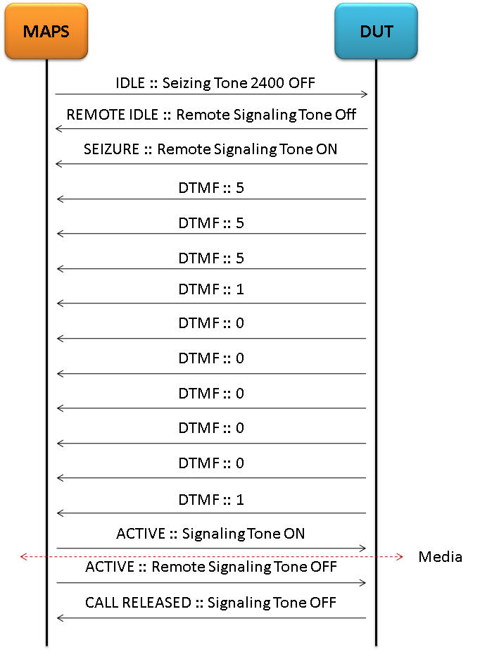
The following are the examples of Call Supervision in SF Tone on Active Mode and Idle Mode:
- The caller’s DTMF digits is superimposed on the signaling tone as it is inserted when seizing the channel.
- The calling side seizes the line by dropping the signaling tone (Line seizure state). At this point, addressing tones are exchanged according to the signaling standard.
The following call flows illustrate the SF Signaling procedure in Active Mode using MAPS™ CAS
|
|
| SF Signaling Place Call Message Sequence
(ACTIVE Mode) |
SF Signaling Answer Call Message Sequence (ACTIVE Mode) |
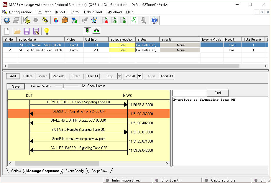
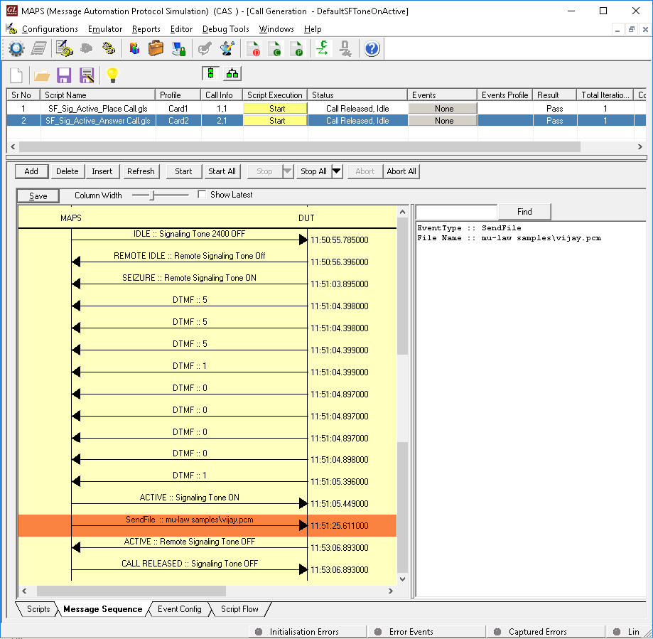
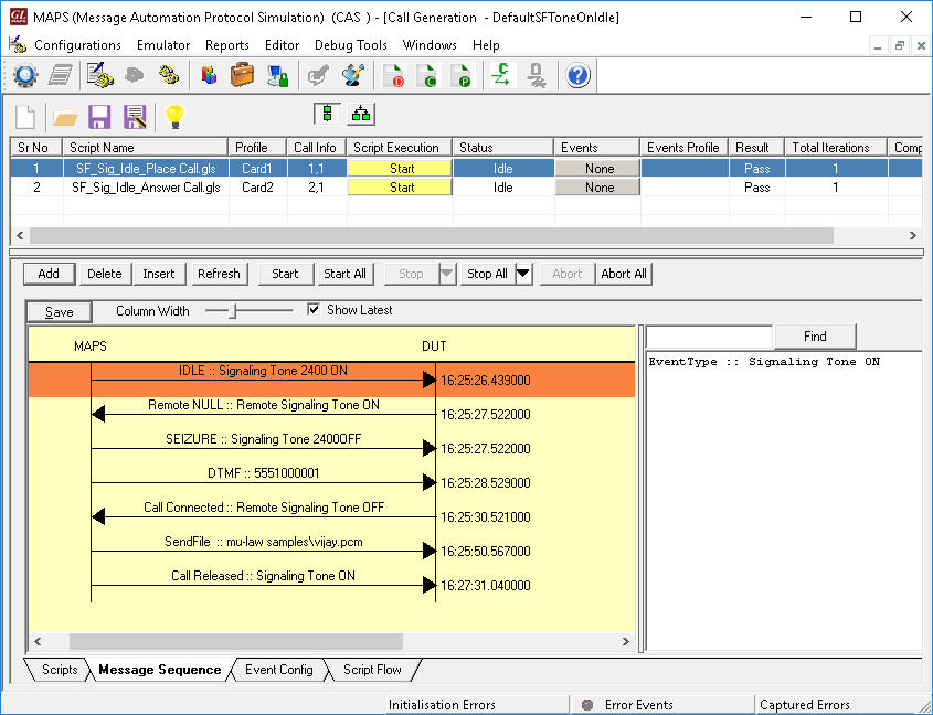
MAPS™ CAS SF Signaling can place and answer call (in both Active mode and Idle modes)on the selected timeslot and Send or Receive Traffic over established call.
|
|
| SF Signaling Place Call Simulation (ACTIVE Mode) |
SF Signaling Answer Call Simulation
(ACTIVE Mode) |
|
|
| SF Signaling Place Call Simulation (IDLE Mode) |
SF Signaling Answer Call Simulation (IDLE Mode) |
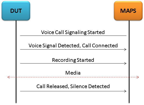
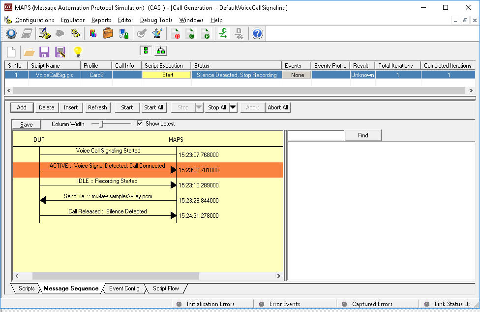
Voice Call Signaling
Voice call lines are typically used for four-wire, point-to-point, two-way voice calls. A Voice detect (VOX) circuit is used on the receive pair to detect incoming audio and signal the voice switch. No signaling is used on the transmit pair. These calls are sometimes configured on 2w circuits.
MAPS™ CAS supports Voice Call Signaling by providing voice activated circuitry (VOX) to control voice connectivity and ensure immediate activation of the circuit upon receipt of incoming voice. During out-going call, it seizes (open) any circuit designated by the Government as a voice call line and transmits the voice into the circuit, whenever the circuit is activated.
User configurable VOX threshold, exhibit a voice signaling threshold of -26 dBm0 (nominal test level) and blocks responses to voice signals below the threshold of -26 dBm0 for the analog G/G interface. The ready scripts used can detect events and respond with appropriate actions with respect to the states.
The following depicts the typical Voice Call Signaling procedure simulation using MAPS™ CAS
|
|
| Voice Call Signaling Message Sequence | Voice Call Recording |
SS5 / ATS No.5 Signaling
MAPS™ CAS supports Signaling System No 5 Line and register signaling procedure simulation as per Q.140- Q.199. SS5 specifications. SS5/ATS-No.5 call simulation is automated with ready-to-use scripts and facilitates to add events on active calls.
ATS-No.5 is a variant of SS5 signaling system, which is used in order to Seize a line, clear a line from either calling or called user side, block a line and answer a call. Line signals use one or two tones. VCSs are able to distinguish between different line signals by keeping track of the call state during the call setup or clearing procedure. Line signals can be sent from either side of an inter-VCS link. ATS-No.5-line signals are compelled implying that each line signal sent in one direction has a corresponding acknowledgement line signal in the opposite direction.
The following call flows illustrate the SS5 Signaling procedure.
|
|
| CAS SS5 Signaling Place Call | CAS SS5 Signaling Answer Call |
MAPS™ CAS SS5 Signaling can place and answer call on the selected timeslot and Send or Receive Traffic as shown in the below screenshots.
|
|
| SS5 Signaling Place Call | SS5 Signaling Answer Call |
A Typical MAPS™ CAS Test System
A typical MAPS™ CAS consists of :
- A Python/Java interface communicating over TCP/IP to a Rack PC with T1/E1 Analyzer Software.
- The Rack PC consists of MAPS™ Client IFC, MAPS™ CLI Server, T1/E1 Analyzer Software (including Windows Client Server software) and a Dual T1/E1 Card.
- Python/Java Client – Acts as User Interface, which executes Python/Java Scripts.
- MAPS™ Python/Java Interface (MAPS Client IFC) – acts as an interface between MAPS™ CLI Server and its Python/Java client Python. It interprets the Python/Java commands and forms the appropriate command as understood by MAPS CLI Server and vice versa.
- MAPS™ CLI Server is an executable that inherits all features of MAPS™ without GUI. It listens to a TCP message socket to receive and execute commands from client and sends the responses back to client.
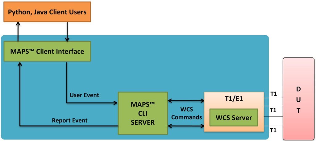
T1/E1 Windows Client Server - Windows Client/Server software performs all CAS emulation primitives including signaling, tone detection, call progress signals, file transfer, and many more functions.
In CLI, MAPS™ Server constitutes two server modules, namely MAPS™ CLI server and GL WCS server.
- MAPS™ CLI Server
MAPS™ CLI Server is an executable which inherits all features of MAPS™ without the graphical user interface. Instead, it listens to TCP message socket to receive and execute commands from the client and sends the responses back to the client. - GL's Windows Client Server
GL's Windows Client/Server software allows the user of T1/E1 analysis cards the capability of remote operation, automation, and multi-site connectivity.
Python client receives report event from the CLI server as shown in the below screenshot.
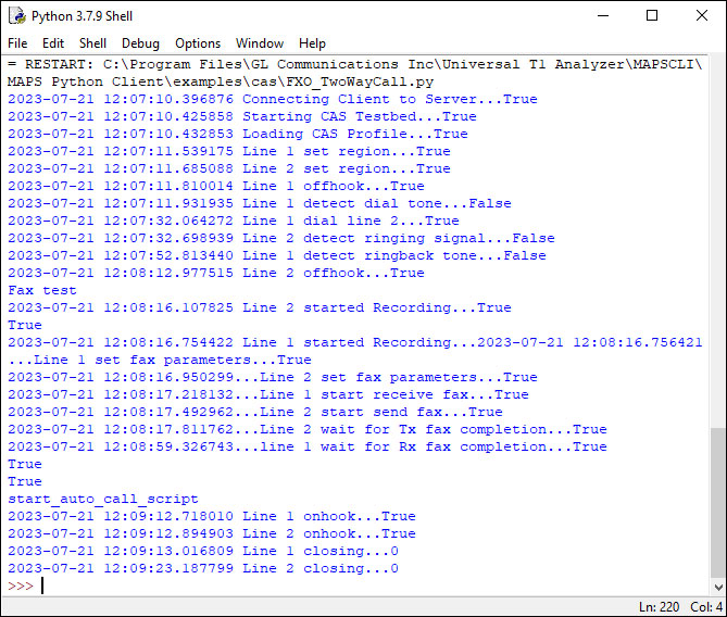
Python client receives report event
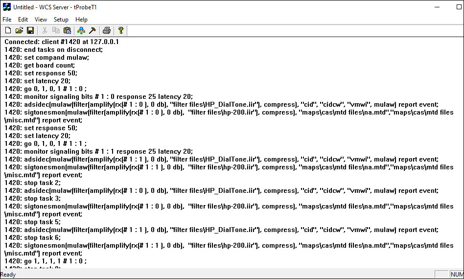
WCS Server Log
Resources
Please Note: The XX in the Item No. refers to the hardware platform, listed at the bottom of the Buyer's Guide, which the software will be running on. Therefore, XX can either be ETA or EEA (Octal/Quad Boards), PTA or PEA (tProbe Units), XUT or XUE (Dual PCIe Express) depending upon the hardware.
| Brochures |
|---|
| MAPS™ CAS - Brochure |
| MAPS™ CLI - Brochure |
| 2Wire Analog Bulk Call Generator - Brochure |
| TestShell / CLI Architecture for Voice Feature Testing |
| Presentations |
|---|
| CAS Signaling Traffic Emulation MAPS - Presentation |
| Signaling and Traffic Simulation using MAPS - Presentation |
GL’s suite of “Wireless Networks |