GUI Based Echo Canceller Testing
Delay/Attenuate Timeslots
- Overview
- Delay/Attenuate Timeslot Dialog Menu
- Understanding Delay in the Delay/Attenuate Application
- Delay Attenuate Timeslots with Very Low Echo Path Delays (for HD boards only)
- Resources
Overview
This application allows you to apply delay, attenuation, and/or filtering to a received signal on any number of timeslots. Delay/Attenuate Timeslots is an "input-process-output" application, that is, a block of data is retrieved from the Rx Data Source; is processed by delaying, attenuating, and/or filtering it; and then retransmitting the processed block on the Tx Destination. You may also mix in additional signals from a number of sources, including
- Speech and/or Noise signals from files
- Speech signals inserted via VF input
- Gaussian noise signals generated internally
Transmitted signaling bits may be Onhook/Offhook, user-specified, or passed through from received to transmitted timeslots.Click here to view the Delay/Attenuate Timeslots screen.
The Delay/Attenuate Timeslots application may receive and transmit on either one or two boards. There are a number of different operating configurations, the most common and useful are:
- Looping back a processed signal - Applying delay, attenuation, and filtering to a received signal and retransmitting the processed signal on the same board on which it was received. Speech and/or noise may also be mixed in. Click here to view a diagram of this configuration. Note that the layout of the Delay/Attenuate Timeslots application dialog closely matches with this diagram.
- Applying pure delay to a signal. A received signal is delayed before being retransmitted.
- Inserting a Simulated Echo Loop. A two-board system is inserted into a T1 or E1 trunk and is used to simulate an echo path having known characteristics. Click here to view a diagram of this configuration.
The layout of the Delay/Attenuate Timeslots application has been designed to closely resemble the above block diagrams. Click here to view an illustration of this resemblance for one such configuration.
Delay/Attenuate Timeslots Dialog Menu
This section describes the operation of the controls in the Delay/Attenuate Timeslots dialog.
- Selecting Time Slots
- Selecting Source and Destination Options
- Setting Delay and Gain/Attenuation
- Selecting a Filter or Transfer Function in Rx Data Source pane
- Controlling Transmitted Signaling Bits Function in Rx Data Source pane
- Mixing in Speech Signals
- Mixing Noise Signals
- Initiating Delay Attenuation Process
- Synchronizing process with incoming Power Burst
- Saving and Loading Configuration
- Process Option
1. Selecting Time Slots
For T1 systems, timeslots range between 0 to 23 and for E1 systems, it range between 0 to 31. For E1 systems, timeslot zero does not carry data, and is therefore off-limits. For E1 systems using CAS signaling, timeslot 16 carries frame alignment and signaling bits patterns, and is therefore also off-limits.
One or more timeslots may be processed by this application. The user must always work with groups of consecutive timeslots if selecting more than one.
The user can also transmit on the same timeslots as those on which the user receive, although the boards may differ.
Click here to view screen capture of the timeslots controls.
2. Selecting Source and Destination Options
If the source and destination cards are the same, you are essentially using this application to create a serial data processing pathway. For example, this is often done, to simulate an echo loop that might arise from a hybrid. See configuration Looping back a processed signal in the overview section above.
If the source and destination cards are different, then you are essentially using the application to create a parallel processing pathway, such as is diagrammed in Inserting a Simulated Echo Loop in the overview section. In this case, the processed signals will be mixed with the signals arriving on the corresponding timeslots of the Tx Destination Card. The text '* Mixes with Rx signal' appears on the screen below the Tx Destination Card list box to remind you of this process.
In addition to source and destination cards, specify the decoding law to be used to expand the incoming signal , and the encoding law used to compress the processed signal prior to transmission.
NOTE: For 'pure delay' applications, the Source and Destination cards must be the same. By default A-Law for E1 systems or Mu-Law for T1 systems is automatically selected. Expansion and compression is not done if the application is set as a delay element.
Click here to view a screen capture of this dialog.
3. Setting Delay and Gain/Attenuation
The incoming signals can be delayed by up to two seconds using the delay controls. The application supports two delay ranges: up to 200 ms., and up to 2 sec. The application enforces a minimum delay time equal to four multiframes ('superframes') duration.
Note that delay is always applied to the Rx data stream(s), and is separate from any delays arising from any filters that may be used.
Click here to view a screen capture of the Delay/Gain Attenuation controls.
Apply gain or attenuation to the received signal(s) using the Gain controls in the Rx Data Source control group. Use positive numbers for gain and negative numbers for attenuation. Up to 40 dB of attenuation or up to 20 dB of gain may be applied.
The Delay and Gain/Attenuation controls remain active while the dialog is processing data (the 'Start' button has been pressed). This allows you to change the delay while the application is in progress.
4. Selecting a Filter or Transfer Function in Rx Data Source pane
A filter or transfer function be applied to the received signal(s) by naming the file containing the filter coefficients in the Filter box. For the purposes of this discussion, the word 'filter' may mean a FIR or IIR digital filter or a general transfer function. GL Communications supplies several FIR and IIR filters, along with transfer functions for all hybrid models specified in ITU-T G.168 with this application.
Click here to view this dialog. Use this 'Browse' button to navigate to the directory where your filter files are stored.
5. Controlling Transmitted Signaling Bits Function in Rx Data Source pane
The Delay/Attenuate Timeslots application provides a number of options for controlling the signaling bits that are transmitted. Applying signaling bits is the last action performed by the application prior to transmitting the processed signal(s). Click here to view a screen capture of these options.
The options are:
- Don't Care - Signaling bits are not controlled. For E1 systems using CCS signaling, this is the only valid option
- Clear Channel - 'Clear Channel' forces the applicable timeslot into the clear-channel condition regardless of any previous commands from any other clients or task threads, which simply states that a process has no interest in the signaling bits being transmitted
- Off Hook/On Hook - The Off Hook or On Hook signaling bits pattern as defined in T1 or E1 configuration will be transmitted. Be sure to set the Off Hook and On Hook values in T1 or E1 configuration before selecting these options, as the values that are current at the time of selection are the ones that will be used.
- Pass-Thru - The incoming signaling bits received on the source card are retransmitted at the T1 or E1 output. This mode is commonly referred to as 'pass-through' or 'transparent' mode in GL Communications Inc. documentation
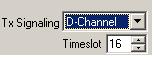
- D-Channel - The D-channel defines the timeslot that carries synchronization information using ISDN D-channel signaling. Click here to view a screen capture of this option
- User-Defined - You define the signaling bits to be transmitted explicitly. When you select this option, the dialog displays push buttons that you can use to establish the desired signaling bits pattern. The user-defined signaling bits pattern is remembered by the application, so that if you select, for example, On Hook signaling and then return to the user-defined option, the previously defined user-defined pattern will be remembered. The pattern is cleared when the application is exited. Click here to view a screen capture of this dialog
The Tx signaling control remains active while the dialog is processing data (the 'Start' button has been pressed). This allows you to change the transmitted signaling bits pattern while the application is in operation.
6. Mixing in Speech Signals
This application provides a number of ways by which voice or other signals may be mixed in with signal(s) received on Rx timeslots. These additional signals may be retrieved from a file (in which case they need not be voice), or may be input via a telephone handset through the VF input of the Tx Destination card. The addition of these signals is specified by controls in the Mix Speech section of the dialog.
Note that speech is mixed in after the received signal(s) have been delayed, attenuated, and filtered. The speech signal may be independently amplified or attenuated using its own Gain box and slider. The same speech signal is mixed into each timeslot being processed.
Mixing Speech from a File
Click here to view screen capture of the dialog controls. For the
purposes of discussion, this file will be referred to as the Speech File regardless of whether or not it actually contains a voice signal.
When the 'Speech from File' option is selected, all those controls relating to file transmission characteristics are activated.
These include:
- Select a speech file for mixing using browse button
- Specify whether the file is to be transmitted exactly once, or whether it should retransmit from the beginning upon reaching the end
- File Gain/Attenuation controls allow you to independently attenuate or amplify the file signal
- Pause/Inhibit Button allows you to mix speech whenever required; it acts as a 'Pause' switch, but affects Speech mixing only
Mixing Speech from VF Input
When VF Input has been selected for mixing retrieving a signal from VF input for processing and mixing with other signals will be referred to as 'VF Insertion' in this discussion. The VF signal is always obtained from the Tx Destination board and is inserted into the receive timeslot specified in the Mix Speech Timeslot box. Analyzer's VF Insert function must be disabled in order to mix speech from VF input using Delay Attenuation Timeslot.
When the 'Speech from VF Input' option is selected, all the controls relating to VF Input transmission are activated. These include:
- VF Input Timeslot. Select the timeslot to be used for VF Insertion here. You may either type the timeslot number into the box, or you can click on the timeslot spinner at the right of the box
- Gain/Attenuation. These controls are the same as those used for the Speech from File option. They allow you to independently attenuate or amplify the VF Insertion signal. You can set the gain or attenuation in one of two ways
7. Mixing in Noise Signals
This application provides a number of ways by which noise or other signals may be mixed in with signal(s) received on Rx timeslots. These additional signals may be retrieved from a file (in which case they need not be noise), or may be inserted directly via a built in Gaussian Noise generator. The addition of these signals is specified by controls in the Mix Speech section of the dialog.
Note that noise is mixed in after the received signal(s) have been delayed, attenuated, and filtered. The noise signal may be independently amplified or attenuated using its own Gain box and slider. The same noise signal is mixed into each timeslot being processed when the Noise from File option is selected. When the White Noise option is selected, each timeslot receives a unique noise signal, but the statistical characteristics of all applied noise signals are identical.
Mixing Noise from a File
Click here to view a screen capture of the dialog controls. For the purposes of discussion, this file will be referred to as the Noise File regardless of whether or not it actually contains a noise signal (it could contain voice). When the 'Noise from File' option is selected, all those controls relating to file transmission are activated. These include:
- Select a noise file
- Specify whether the file is to be transmitted exactly once, or whether it should retransmit from the beginning upon reaching the end
- File Gain/Attenuation - These controls allow you to independently attenuate or amplify the file signal. Click here to view a screen capture of the gain controls
- Pause/Inhibit Button - Allows mixing noise whenever required. It acts as a 'pause' switch, but affects Noise mixing only
Mixing in White Noise
Click here to view a screen capture of the dialog controls. The term 'White Noise' is used interchangeably with 'Gaussian Noise' in this discussion.
When the 'White Noise' option is selected, all those controls relating to noise generation and transmission are activated. These include:
- Noise Level - These controls replace those used for the Noise from File option. They allow you to independently set
the level of the noise signal.
The Level controls remain active while the dialog is processing data (the 'Start' button has been pressed). This allows you to change noise level while the application is in operation. - Pause/Inhibit Button. - Allows mixing of white noise whenever required
8. Initiating delay attenuate process
Transmit and Receive buffer latencies are continually displayed in the status box to the right of the Run LED. Click here to view a screen capture of this dialog. If there are errors during processing, the status box will also display an error count.
9. Synchronizing Start Processing with Incoming Power Burst
You may sometimes want to synchronize the process with the arrival of significant power on the selected timeslots. This feature provides a capability to save and retrieve configuration settings options. Click here to view a screen capture of this data box.
When you specify this option the application waits until it sees a signal with the specified power on selected Rx timeslots before proceeding. Further, if the total power received on all selected timeslots exceeds this level, the application will commence processing. For this reason, it is important toset the Burst Threshold high enough to avoid false triggering but low enough to trigger when a valid triggering signal is presented.
10. Saving and Loading Configurations
This feature provides a capability to save and retrieve configuration settings. options. Click here to view a screen capture of these buttons.
Saving a Configuration
Click here to view the screen. Using this dialog, you may navigate to the directory in which you want the configuration to be saved, name the configuration, and save it to disk.
Configurations are stored in Microsoft® Archive File format, with default file name extension '.ar', if file name extension is not specified.
Loading a Configuration
The user can load a previously saved configuration by pressing the Load button in the configuration section. Using this dialog, the user can navigate to the directory where the configuration has been stored, select the appropriate configuration archive, and indicate the archive to be loaded.
11. Process Options
The delay attenuate processing options providesoptions provide the user to define various settings such as Hardware Buffering, Processing Blocksize, Transmit Latency , Run Level, Minimum Achievable Delay, and USB buffering specification. Click here to view the screen.
Resources
Please Note: The XX in the Item No. refers to the hardware platform, listed at the bottom of the Buyer's Guide, which the software will be running on. Therefore, XX can either be ETA or EEA (Octal/Quad Boards), PTA or PEA (tProbe Units), XUT or XUE (Dual PCIe Express) depending upon the hardware.
| Item No. | Item Description |
| XX062 | Echo Path Delay/Loss Simulation Software |
| Related Software | |
|---|---|
| XX020 | Record and Playback of Files |
| XX051 | Synchronous Trunk Record Playback |
| XX051 | Synchronous Trunk Record Playback |
| XX022 | Dial DTMF/MF Digits Software (optional) |
| XX031 | Enhanced T1 / E1 Call Capture/Analysis Software |
| XX063 | Echo Path Delay/Loss Measurement Software |
| XX065 | G.168 Echo Canceller Test Suite |
| XX066 | Digital Echo Canceller |
| XX067 | Automated Echo Canceller Testing with or without VQT |
| XX068 | Semi-automated Scripted EC Testing |
| PKB070 | Audio Processing Utility |
| PKB081 | Automated Acoustic Echo Cancellation (AEC) Compliance Test Software |
| Related Hardware | |
| PTE001 | tProbe™ Dual T1 E1 Laptop Analyzer with Basic Analyzer Software |
| HDT001/HDE001 | Legacy HD T1 or E1 (PCI) Cards with Basic Analyzer Software |
| UTE001 | Portable USB based Dual T1 or E1 Laptop Analyzer |
| Recommended Accessories | |
| SA013 | T1 / E1 On Site Training Class (not including travel or hotel) |
| SA021 | File Edit Software |
| SA026 | Adobe Audition Multitrack Sound File Viewing and Editing Software |
| SA048 | Goldwave Software |
| SA017A | RJ48C to RJ48C Straight Cable, 10ft. cable |
| SA017A | RJ48C to RJ48C Crossover Cable, 10ft. cable |
| SA008a | Handset Adapter with Handset |
| SA022 | Extended 1 Yr. Software Upgrades and Hardware Warranty, and Comprehensive Support for Basic and Optional Software |
 Back to Echo Canceller Testing Solutions Main Page