Digital Echo Canceller
Overview
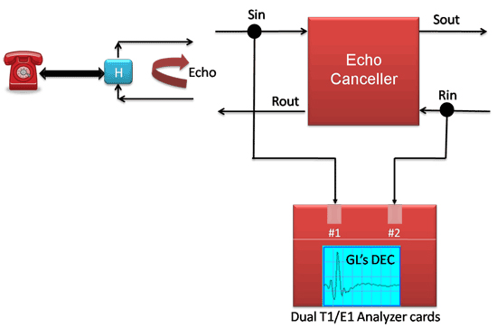
A Digital Echo Canceller is a four-port device that supports bidirectional voice traffic between the two ends of a connection. The two ends of the connection are referred to as the far end and the near end. Voice signals from the far end are carried to the near end on the receive path. Voice signals from the near end are carried to the far end on the send path. Note that the signal pathways are labeled from the point of view of the near end. A typical configuration is shown in the figure below.
The picture above indicates conversation between two distant persons. The signal traverses the receive path into the echo canceller's Rin port, which monitors the signal and forwards it along through its Rout port.
The signal continues unaltered to the hybrid, a device that interfaces the PSTN's four-wire circuit to the two-wire subscriber line. This interface is not perfect, resulting in a reflection of a portion of the signal energy being reflected back into the four-wire circuit. This reflection manifests itself as echo, a delayed, attenuated and dispersed version of the original speech signal, which traverses the send path back to the original speaker. In some cases where, the echo is significantly delayed, it can be very annoying to the far end speaker, to the point of interfering with the conversation.
The function of the echo canceller is to detect and remove the echo. It does this by estimating the transfer function of the hybrid that produces the echo, which it accomplishes by comparing the echo to the original signal. The process of generating the estimate is normally iterative in nature -more the signal is seen, more refined is the estimate.
The estimated transfer function is referred to as the echo path model. The process of refining the echo path model as more and more signal is seen is referred to as adaptation. When adaptation has proceeded to the point that a reasonably good estimate has been calculated, the echo canceller is said to have converged. The speed with which the echo canceller converges, and how accurate the echo path model is, are crucial measures of the echo canceller's performance in a network.
Once a reasonable echo path model has been calculated, the echo canceller can predict the echo that will result from the far end signal that it is monitoring. It can thus remove that echo by subtracting it from the signal on the send path (that is, by subtracting the estimated echo from the actual echo).
Main Features
- Allows real-time and offline processing
- Interfaces directly with A-Law or m-Law encoded signals
- G.168-2000 compliant, tests 2A, 2B, 2C, 3A, 3B, 3C, 4, 5, 6, 7
- 16, 32, 64 or 128 ms tail length; programmable tail offset
- Comfort noise generator with adaptation to background noise level
- Echo path visibility
- Continuous reporting of echo path delay, ERL, and dispersion
- Event logging
Configuration For Monitoring in Digital Echo Canceller
Cross-connect port1 and port2 of T1/E1 cards
Monitor Rin and Sin using two Y Bridges, a straight and a Turn Over Cable on Card #3 and Card #4 (Port 3 and Port 4 can be on the same PC or a different PC)
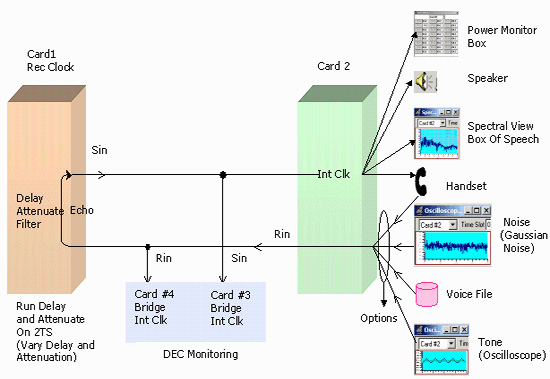
You need two Dual E1/T1 cards. These two cards can be on the same PC or on different PCs.
Port 1 configuration: Terminate, Rec Clk, No Loopback
Port 2 configuration: Terminate, Int Clk, No Loopback
Port 3 configuration: Bridge, Int Clk, No Loopback
Port 4 configuration: Bridge, Int Clk, No Loopback
same framing format for all the ports.
- Connect a Y bridge say 'A' to port1 and another Y bridge say 'B' to Y bridge A
- Cross connect port1 through y bridge A and port 2
- From the two ports of Y bridge B connect a straight cable (green) to port4, and the other port of Y bridge B - cross connect cable (yellow) to port3 - You should see no alarm (red or yellow) on all the monitor windows
- Invoke Digital Echo Canceller Set Sin on port3, Rin on port 4.
Rin is the in of the receive path.
Sin is the in of the send path.
Disable (gray out) Rout and Sout - as transmit is disabled in the bridge mode.
Set EC tail in the Provisioning tab to 128. - To provide stimulus continuously broadcast "Digital Echo Canceller\gnoise_with_silence-10.ula" on ts 1-3 from port 2
- Port1 emulates echo path, open Delay and attenuate application on port 1 and set delay to say 40 ms, attenuation to -10 db (ERL should be a min of 6db, ERL is the attenuation of a signal from Rout to the Sin of the Echo canceller, due to loss in the echo path) Select Ts 1-3. Choose m11 filter (just an example!)
Run Digital Echo Canceller Simulation, click on Enable Echo canceller, click on Enable Adaptation change delay to 50ms see the changes in the adaptation, see the adaptation change to 50 ms in the statistics and logging window. Disable adaptation, change delay to 60 ms, see that there is no change. Enable adaptation and see the changes in the adaptation. In the logging page check EC convergence, EC Reconvergence, Enable log file tabs.
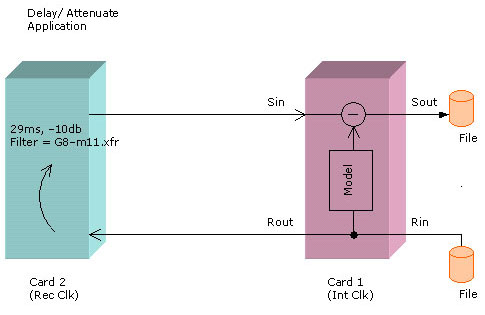
Single Ended Configuration for Testing Digital Echo Canceller
Settings for DEC Port (Port1): Terminate, Int Clk, No Loopback
Echo loop Port (Port2): Terminate, Rec Clk, No Loopback
Same framing format for all the ports.
- Cross connect port1 and port 2 - You should see no alarm on all the monitor windows
- Invoke Digital Echo Canceller , To provide stimulus Set Rin file - use " gnoise_with_silence-10.ula" file from the Digital Echo Canceller directory
- Set Rout and Sin in card1, Rin and sout are not used (greyed out) Set EC tail in the Provisioning tab to 128
- Port2 emulates echo path, open Delay and attenuate application on port 2 and set delay to say 29 ms, attenuation to -10 db Select Ts 1-3, Choose G8-m11.xfr filter
- Run Digital Echo Canceller Simulation, click on Enable Echo Canceller, click on Enable Adaptation, change delay to 50ms see the changes in the adaptation. Observe the adaptation change to 50 ms in the statistics and logging window
Single Ended Configuration Useful to Demo DEC
DEC Application for Analog and Mobile Interfaces
Interface
Timeslot Selection - Designate the timeslots on which echo cancellation has to take place by selecting the corresponding timeslot buttons.
I/O Source and Destination Selectors
Echo Cancellers are 4-port devices, with ports designated as follows. Select either a card (online operation) or a file (offline operation) as a port.
Receive Path Ports:
- Rin: Receive path input port. In this case, data from the source will be routed to the echo cancellers of each selected timeslot
- Rout: Receive path output port. You do not have to specify a destination, in which case all Rout output is discarded
Send Path Ports:
- Sin: Send path input port. In this case, data from the source will be routed to the Sin port of each selected timeslot's echo canceller
- Sout: Send path output port. You do not have to specify a destination, in which case all Sout output is discarded
Other Options
- Enable Echo Canceller: Selecting this tab, the echo cancellers of all selected timeslots are enabled
- Enable Adaptation: Selecting this tab, the adaptive mechanism of the echo cancellers on all selected timeslots is enabled
- Enable NLP: Selecting this tab, the non-linear processors (NLPs) of the echo cancellers of all selected timeslots are enabled
- Enable DTD: Selecting this tab, the double-talk detector of the echo cancellers on all selected timeslots is enabled
These buttons remain active during operation of the echo cancellers, so that you may enable or disable the modules during the process. Note that the modules are enabled or disabled on all selected echo cancellers.
The various tabs provided under DEC Simulator are:
- Provisioning: This tab is used to set echo canceller operating parameters such as Timeslot Selection, I/O Source and Destination Selectors, and Operating parameters
- View: This tab is used to get an in-depth view of the operating conditions of a single echo canceller using graphs that display transfer function in Time domain and in Frequency domains
- Statistics: This tab is used to view statistics of ERL, delay, dispersion, FSTA, NSTA, FLTA, and NLTA of all active time slots
- Logging: This tab is used to specify logging and reporting features
- About: This option tab contains copyright and version information
Provisioning
The Provisioning tab allows you to set various operating parameters for various echo canceller components:
- Adaptive Subtractor (EC Tail) - functions are to calculate the transfer function of the echo path and, once a reasonable estimate of the echo path has been calculated, it will cancel echo by subtracting the estimated echo from the signal arriving at Rin from the actual echo appearing at Sin
- Double-Talk Detector - Double-Talk is the condition where speakers at both ends of the line are talking simultaneously. That is, voice traffic is present on Receive and Send paths (at Rin and Sin) simultaneously. It is essential that the Echo Canceller detects double talk situations because adaptation can only occur when it detects a voice signal on the Receive path and the echo of that signal on the Send path. The Double-Talk detector in this system is triggered by a sudden rise or fall in the power of the Sin signal
- Non-Linear Processor - The function of the Non-Linear Processor is to mitigate residual echo.
- Tone Detector - The tone detector prevents the echo canceller from attempting to converge in the presence of narrow-band signals
- Comfort Noise Generator - The comfort noise generator, when enabled, injects noise on the Sout line. The CNG attempts to match the comfort noise level to the Sin power level, up to the maximum power level specified in the entry box
View
The View page gives enhanced visibility of echo canceller operations. Select the echo canceller timeslot to be viewed.
This 'View' presents the Echo Canceller's calculated transfer function. You can view the transfer function in either time or frequency domains. This also allows to pan or zoom the display, or to display coordinates.
This also indicates adaptation, double-talk, and presence of signal at Rin and Sin via LEDs. A sample View Page is displayed in figure below:
Transfer Function Graph
A graphical representation of the transfer function is shown in the large blue field. In the figure a time-domain transfer function is depicted.
Immediately below the transfer function graph are buttons that are used to manipulate the graph.
- Zoom: activates the Zoom Tool. Using this tool, you can define a zoom area on the graph by clicking and dragging from one corner to the diagonally opposite corner of the graph. Releasing this button unlatches the Pan and P(x,y) buttons
- Pan: activates the Pan Tool. Use this tool to grab and fix the display with the mouse pointer. Releasing this button unlatches the Zoom and P(x,y) buttons
- P(x,y): activates the CoordinateTool. You can use this tool to read out the coordinates of any point on the graph. Releasing this button unlatches the Zoom and Pan buttons
- Undo: is used to return the graph to its full display size and position
- H(T): this helps the echo canceller's calculated transfer function to be displayed in the time domain. This is the default display domain. Releasing this button unlatches the H(F) button
- H(F) Button: this causes the echo canceller's calculated transfer function to be displayed in the frequency domain. Releasing this button unlatches the H(F) button
Indicator Lamps
All lamps are dark when the application is in standby mode. The indicator lamps are active for Adaptation, Rin/ Sin Signals, and Double Talk when run is in progress.
Statistics
This displays various statistics for all active echo cancellers. A sample screen is as shown in the figure.
The following statistics are presented:
- ERL: (Echo Return Loss), the industry term for the attenuation implicit in the echo path. In the case of the GL digital echo canceller, the ERL reported is actually that of the echo path model. ERL is reported as negative gain in dB
- Delay: The mean delay experienced by the signal as it traverses the echo path. In the case of the GL digital echo canceller, the delay reported is computed by a method of moments. To be exact, the delay is the root mean value of the squares of the calculated echo path coefficients, each coefficient being waited by its individual delay
- Dispersion: A measure of the 'spread' experienced by the signal as it traverses the echo path. In the case of the GL echo canceller, dispersion is reported as four standard deviations of the signal delay when calculated as described above
- FSTA: Far end Short-Term Average power of the signal as measured at Rin. Reported in units of dBm
- NSTA: Near end Short-Term Average power of the signal as measured at Sin. Reported in units of dBm
- FLTA: Far end Long-Term Average power of the signal as measured at Sin. Reported in units of dBm
- NLTA: Near end Long-Term Average power of the signal as measured at Sin. Reported in units of dBm
Logging
Logging helps to report various conditions and events in an *.txt or *.csv file formats. Note that logging is active only when an execution is in progress. A sample logging screen is as shown in the figure below.
The sections of Logging are described below:
- When Report Status at Regular Time Interval is checked, the status of all active echo cancellers is reported at regular time intervals. The reported status includes the echo canceller convergence and double-talk status, and the calculated echo path measures (ERL, delay, and dispersion)
- The reporting can also be configured to occur when EC has converged, when EC needs a reconverge, and/ or when EC detects a double-talk condition
Digital Echo Canceller Demonstration
Digital Echo Canceller Demonstration
- Echo Path Simulation
- Echo Path Estimation
- Echo Path Modeling
Resources
Please Note: The XX in the Item No. refers to the hardware platform, listed at the bottom of the Buyer's Guide, which the software will be running on. Therefore, XX can either be ETA or EEA (Octal/Quad Boards), PTA or PEA (tProbe Units), XUT or XUE (Dual PCIe Express) depending upon the hardware.
| Item No. | Item Description |
| XX066 | Digital Echo Canceller |
| Related Software | |
|---|---|
| XX020 | File Record/Playback Software |
| XX051 | Synchronous Trunk Record Playback |
| XX022 | Dial DTMF/MF Digits Software (optional) |
| XX031 | Enhanced T1 / E1 Call Capture/Analysis Software (optional) |
| XX062 | Echo Path Delay/Loss Simulation Software |
| XX063 | Echo Path Delay/Loss Measurement Software |
| XX065 | G.168 Echo Canceller Test Suite |
| XX067 | Automated Echo Canceller Testing with or without VQT |
| XX068 | Semi-automated Scripted EC Testing |
| PKB070 | Audio Processing Utility |
| PKB081 | Automated Acoustic Echo Cancellation (AEC) Compliance Test Software |
| Related Hardware | |
| PTE001 | tProbe™ Dual T1 E1 Laptop Analyzer with Basic Analyzer Software |
| UTE001 | Portable USB based Dual T1 or E1 Laptop Analyzer with Basic Analyzer Software |
| HDT001/HDE001 | Legacy HD T1 or E1 (PCI) Cards with Basic Analyzer Software |
| Recommended Accessories | |
| SA013 | T1 / E1 On Site Training Class (not including travel or hotel) |
| SA021 | File Edit Software |
| SA026 | Adobe Audition Multitrack Sound File Viewing and Editing Software |
| SA048 | Goldwave Software |
| SA017A | RJ48C to RJ48C Straight Cable, 10ft. cable |
| SA017A | RJ48C to RJ48C Crossover Cable, 10ft. cable |
| SA008a | Handset Adapter with Handset |
| SA022 | Extended 1 Yr. Software Upgrades and Hardware Warranty, and Comprehensive Support for Basic and Optional Software |
 Back to Echo Canceller Testing Solutions Main Page