Network Impairment Simulator
Testing system performance under realistic network conditions requires the introduction of impairments that could be expected to be seen on networks, especially public networks which are uncontrolled. There are a number of ways to do this. A basic method is to use network simulation devices that can emulate conditions expected to be encountered.
Packet loss can include a straight-forward % of packets to be lost to burst models where for an error event a certain number of packets will be disrupted. Latency or packet delay, and jitter, the variance in inter-packet delay, out-of-order packets, duplicate packets, and network congestion are other types of packet impairments expected to be seen. Latency and bit errors are impairments that could be seen on E1/T1 bearers or signaling links.
IP Impairments -
The simplest method of adding real-time traffic impairments to the IP domain is to use network tools such as the GL PacketExpert™, IPLinkSim™, or PacketCheck™ to simulate all network impairment conditions of real world IP networks such as network latency, network delay variation (jitter), bandwidth, congestion, packet loss, packet FCS errors, packet bit errors and others. The link impairments can be applied independently to both directions and can be configured as a bridge to forward frames between the connected networks/end points.
T1/E1 Trunks Impairments -
Real world types of impairments seen by E1 voice bearer traffic and signaling links can be emulated with applications such as the Error Insertion and Bulk Delay application, and T1 E1 HDLC Impairment application that work in conjunction with the GL’s T1 E1 hardware to introduce impairments on selected timeslot or on the entire trunk. This includes impairments such as BPVs, logic errors, frame errors, CRC errors, and FDL errors. This application permits inserting single, fixed, automatic, random, and burst error into the incoming bit stream. This includes a bulk delay feature to simulate network delay on the T1 E1 links and trunks.
Network Impairments - Why?
- Simulate Network Impairments - to characterize Voice, Video, Data, and Image Quality as function of impairments - signal degradation, bit errors, latency (delay), jitter, synchronization errors
- Simulate Traffic Load - to characterize traffic throughput (Voice, Fax, Data, & Video) as a function of Impairment Intensity
- During technology transition from one technology to another, thus helps finding the most cost-efficient technology to meet the required performance.
Following are the GL’s simulators used to introduce impairments in the network:
Impairing Protocol Messages and Traffic using MAPS™
The packet and trunk impairments are applied generically to all traffic on the connections being impaired.
For more specific and detailed testing, MAPS™ applications run scripts to send and receive messages to setup and tear down audio paths using different protocols. As part of this implementation, MAPS™ simulator can select specific messages in the protocol and use logical operators (AND/OR/XOR), DELETE, or INSERT data to corrupt fields in the signaling messages. Impairment can be applied at any position in the given frame using byte offset value. MAPS™ supports low level impairment capability by manipulating forward and backward call messages (on a per call basis) just before sending over transport.
Logical operators can be used to apply a specific impairment to a specific message over the system and impairments can also be set on the RTP path. This requires the user to know where in the frame of a particular message to insert the impairment or to corrupt. The impairment feature is used to impair the parameter values in the selected message template to test error conditions. The user can either enable or disable this option in Send Message command of a particular script.
Simulation of delay error and jitter over Ethernet/IP networks
PacketExpert™ can perform Wire speed BERT (Bit Error Rate Testing) and provides 2 types of Error Insertion into the outgoing Tx traffic - Bit Error Insertion and FCS (Frame Check Sequence) Error Insertion. Bit Error Insertion allows inserting Bit Errors. FCS Error insertion allows sending frames with wrong FCS value. Single Error Insertion as well as Rate Error Insertion is supported. Rate Error insertion includes constant error rate, ranging from 10-1 to 10-9, to be introduced into the outgoing stream. With error insertion, testing QoS characteristics in the network like Bit Error Rate, Throughput, Frame Loss, and Latency is possible.
Impairment Simulation for Ethernet LAN and WAN
- IPLinkSim™ - WAN Emulation with PacketExpert™, and IPNetsim™
Both IPLinkSim™ and IPNetSim™ can simulate all WAN impairment conditions of real world networks such as network latency, network delay variation (jitter), bandwidth, congestion, packet loss, packet FCS errors, packet bit errors and more. The link impairments can be applied independently to both directions.
- IPNetSim™ Handheld
IPNetSim™ Handheld is a hand-held battery operated instrument that can simulate the real-time IP and Carrier Ethernet network dynamics by means of hardware controlled packet delay, loss, jitter, errors, bandwidth limitations, congestion, and duplication. IPNetSim™ Handheld offers to manage network behaviors of up to 1 Gbps rates with accuracy always better than 1ms. IPNetSim™ Handheld is equipped with hardware based impairments generator, and dual GbE ports.
RTP Impairment Generation with RTP Toolbox™
Users can manually introduce impairments and transmit data on the RTP sessions. The impairments that can be generated include
- Latency: Fixed, Uniform, Nominal
- Packet Loss: Periodic, Random, Burst (burst probability and burst size)
- Packet Effects: Out of order, Duplicate Packets
TDM Transmission Impairment
A variety of TDM simulation interface, delay, and error impairment options are provided, including OC-3 / STM-1, STS-1, T3, T1 / E1, 4 Wire Analog, and Two Wire Analog. Scripted operation make it easy to control errors - random and burst.
TDM - information is digitized and sent continuously over channels with maximum required capacity; voice uses circuit switching; data uses a dedicated data networks, video is NOT supported (separate networks).
TDM has complex synchronous and asynchronous digital hierarchy DS0 (64 kbps), T1/E1 (1.544/2.048 Mbps), T3/E3, OC-3/STM-1.
- Timing, transmission, and multiplexing errors propagate thru the multiplexed hierarchy and can manifest in errors, alarms, and jitter
- Bit Errors, BPVs, Frame Errors, CRC Errors, FDL Errors, Loss of Signal, Yellow and Blue Alarms
- Delays much lower, NO queuing, less jitter, NO congestion, also NO sharing of resources
Analog - information is sent in its native format e.g. speech, fax, picture, video. May be digitized and use the TDM network.
Data Link Impairment
HDLC frame impairment can be introduced at T1 and E1 rates. Impairments including Logic Errors, CRC Errors, Drop a Frames, Change Order of Frames, Duplicate a Frames, Insert a Frame, and Delay a Frames can be introduced manually or automatically with a specified random rate.
Satellite channel test, measurement, and simulation
GL offers test tools to analyze and simulate satellite channels across various interfaces. The applications include:
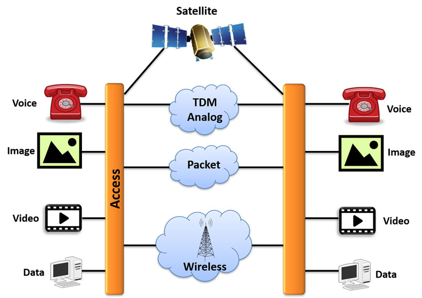
- Wide area connectivity in footprint of the satellite beam - video broadcast and mobile phone applications possible for large populations
- Instantaneous network deployment - voice, data, and video available immediately
- Propagation delay 250 milliseconds (up + down); round trip delay 500 milliseconds
- RF channel is 36,000 km before amplification or repetition - a free space path loss in the range of 190 to 208 dB (for frequencies in the 2 GHz to 15 GHz range)
- Variable channel characteristics; totally absent or severely degraded during sun outages, bursty errors during rain and snow, during clear sky low random/gaussian errors
- Limited bandwidth; available electromagnetic spectrum shared among all users
- Possible interference with adjacent satellites
- Testing Wireless networks - 2G, 3G, and 4G backhaul over satellite
- BER testing across all satellite gateway interfaces
- Satellite delay and error simulation
- Satellite delay compensation
- Round-trip and one way delay measurement
- Echo simulation and echo cancellation testing
- Voice and Data Quality Testing
Microwave Impairments
- line of sight - point to point connectivity; requires terrain clearance
- fast network deployment - voice, data, and video available quickly
- propagation delay minimal
- RF channel may be long before amplification or repetition - a free space path loss in the range of 120 to 150 dB (for frequencies in the 2 GHz to 15 GHz range)
- variable channel characteristics; bursty errors during rain and snow, during clear sky low random/gaussian errors
- limited bandwidth; available electromagnetic spectrum shared among all users
- possible interference from adjacent systems
Fiber Impairments
- Very low error rate and Low loss - single mode fiber single solid core; 1000’s of km before repetition
- Secure, immune to electromagnetic interference
- Synchronous Optical Network (SONET, SDH) time division multiplexing
- Extremely high data rates - terabits / sec
- Low cost LED transmitters, or High power laser transmitters
- Dispersion limits bit distinguishability, and therefore bit error rate
- Fiber optic cables can be fragile, difficult to install
- Prone to fiber cuts, service outages, redundant and diverse transmission necessary
Copper / Cable Impairments
- Electrical wave propagation, high power, heat dissipation, high attenuation (loss), low distance before repetition
- Conversion of information to electrical is easy
- High amplifier noise, frequency and phase distortion, much higher BER vs. Optical BER