T1 E1 Error Insertion & Bulk Delay Application
Overview
Simulating bulk delay and errors like that found in real networks can help optimize the performance of applications. GL's USB based or PCI Card based T1 E1 Analyzers can easily simulate such conditions.
For example:
- At what delay does the application under test suffer throughput degradation due to ARQ - Automatic Repeat Requests
- At what error rates does voice performance on compressed codec circuits start to degrade.
- How good is error correction when the underlying uncorrected error rate is 10E-5
- How can I simulate the error characteristics of a microwave circuit, a copper T1 line, a fiber optic transmission line
- Does encryption multiply the inherent error rate of the circuit and by how much?
The following functions are permitted by GL's Bulk Delay and Error Insertion application:
- Timeslot specific error insertion
- Manual Fixed Error Insertions can be inserted for T1 E1:
- BPVs
- Logic Errors
- Frame Errors
- CRC Errors
- FDL Errors
- Automated Fixed or Random Errors can be inserted at a rate ranging from:
- BPVs 10E-4 to 10E-9
- Logic Errors 10E-2 to 10E-9
- Frame Errors 10E-2 to 10E-9
- CRC Errors 10E-9 to 10E-2
- FDL Errors 10E-9 to 10E-2
- Bulk Delay in microseconds to over a hundred milliseconds; Delay can be varied from 0 to 169.77mS (T1) or 127.99mS (E1) with an accuracy of ± 10uS
- The bulk delay range is 0 -127ms, additional delay can be applied by other software based applications such as the Delay / Attenuate application
Working Principle - Error Insertion
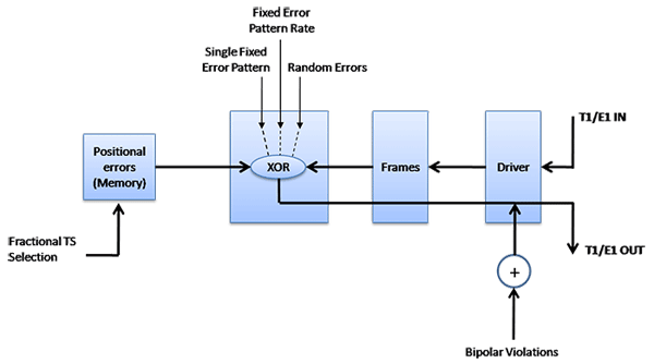
The Error insertion application permits inserting single, fixed, automatic, random, and burst error into the incoming bit stream.
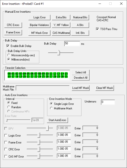
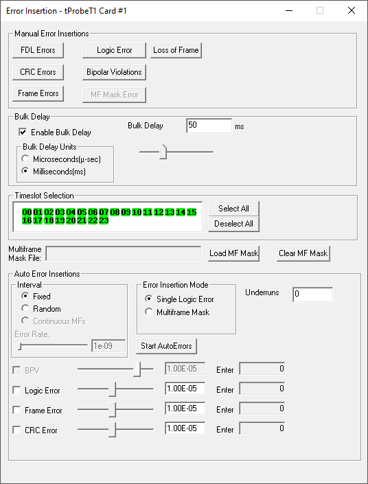
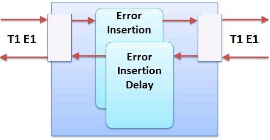
A block diagram, GUI, and schematic of the function is provided above and below. For Error Insertion application, ensure that the analyzers framing format configuration should be set according to the input signal framing format. As shown in the diagram below, the input to the T1 Card is fed back to the output after passing through the error insertion logic.
When the above feature is used in conjunction with "Cross Port Transmit", introducing delays and errors is extremely easy.
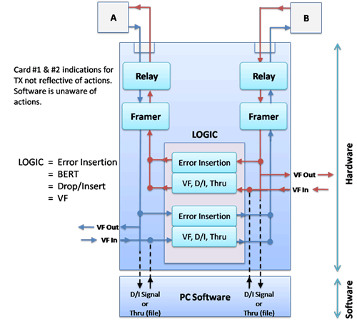
In this Mode, the data that would normally be transmitted on Card 1 (Port 1) is diverted and transmitted on Card 2 (Port 2) and the data that would normally be transmitted on Card 2 (Port 2) is diverted and transmitted on Card 1 (Port 1). The receive paths are completely unaffected. This feature also eliminates complex cabling.
Below is another working example of Error Insertion in Cross-Port Transmit mode and Recovered Clock in different PCs.

The PC #1 and PC #2 is equipped with T1 E1 analyzer, RJ45 cross cables are connected from port #1 of PC #1 to the Port #1 of PC #2 and similarly, Port #2 of PC #1 is connected to Port #2 of PC #2. T1 E1 analyzer on PC#2 is set to Cross-Port Transmit mode and Recovered Clock on both the ports.
Enhanced BERT is running on PC #1, this will transmit BERT Patterns to PC#2. On PC #2, upon receiving BERT Patterns, Error insertion application will insert errors on the received BERT Patterns and the same will be transmitted back to PC #1. User’s can monitor received error and error rates on PC #1 through Enhanced BERT application.
Error Insertion Modes:
The types of error insertions that are supported are listed below.
Multiframe Errors uses a multiframe mask file that was created by the Tx Multiframe application to insert errors. A rate of 102 means that the error multiframe will be inserted every 100th multiframe. It will be necessary to activate all timeslots. With Continuous MFs insertion, the error multiframe mask is inserted into every multiframe that is transmitted.
Auto Error Insertion supports fixed or random insertions.
Manual error insertionFor T1 & E1:
For T1:
For E1:
|
Auto error insertionFor T1:
|
Examples
Bipolar Violations
- Open Monitor T1 E1 line tabs on card2. Open the Error Insertion application on card1.
- Click on Bipolar Violations on error insertion. Observe that bipolar violation is inserted (turns red and then to yellow) and BPV count increments on the 'Monitor T1 E1 line' tab.
MF error:
MF Errors or Fixed Error Injection allows you to insert errors in a very precised manner. You can direct that an error will be inserted in the timeslot and bit position of their choice. It is also necessary to select all the timeslots. If necessary, you can deactivate transmit timeslots that are being used by other applications.
- Start the application, Tx Multiframe.
- Click Reset MF and modify the multiframe by inserting desired values (such as 56).
- Click Save MF and save the multiframe mask to a file say "mf'.
- Open Error Insertion application on card1.
- Click Load MF Mask and Select the saved file mf.
- Click MF Error and observe that frame error turns red on Monitor T1 E1 line tab on card2 and the frame error count increases on the monitor tab.
Working Principle - Bulk Delay
Bulk delay is an added feature in Error insertion application, that allows users to apply delay on the entire T1 E1 trunk (full multi-frame) of 1.544Mbps (T1) pipe or 2.048 Mbps (E1) pipe. This helps to simulate network delay along the T1 E1 links. After selecting or adjusting the delay, the Delay will fill a buffer and begin transmitting the signal; this will cause the T1 or E1 multi-frame signal to briefly lose sync when applying the delay. However, Bulk Delay is not supported in T1 E1 Quad and Octal boards.
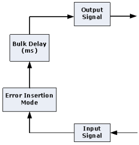
- Bulk delay can be applied in either microseconds or milliseconds units
- Delay can be varied from 0 to 169.77mSec or 69 to 169845 µSec for T1 and 0 to 127.99mSec or 46 to 128042µSec for E1 with an accuracy of ±10µSec.
- The delay resolution is based on the byte increments of T1 or E1 (8 bits at a time)
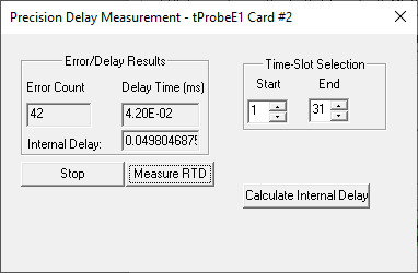
The bulk delay inserted can be verified using the Precision Delay Measurement application. The user can either enter the required delay value manually or can adjust the slider to choose the delay value. To observe the delay set, in the precision measurement window as shown in the screen below the user has to check the Enable Bulk Delay check box. The Precision Measurement window displays default delay difference of 0.04 for E1 card and 0.06 for T1 cards.
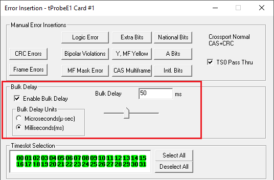
The delay set by the user using the Error Insertion application can be observed in the Precision Delay Measurement application.
Note: Currently this application feature is not available on Octal/Quad T1 E1 Analyzers
 Back to List of T1 E1 Basic and Optional Applications Index Page
