Delay/Attenuate - Single Channel
Overview:
Delay/Attenuate Timeslots - Single Channel Application is an addition to the already existing Echo Test Solutions suite of applications. This application also facilitates Low Delay Echo Path Modeling and applying delay, attenuation (gain), and/or filtering to a received signal on a single timeslot. You may also mix-in additional signals from other sources, including speech signals inserted via VF input. Speech signals inserted via VF input and Gaussian noise signals or Tone generated internally within the application.
Main Features:
- Transmission of data, voice or file on single timeslot
- Multiple instances of the application can be opened simultaneously
- The application can be implemented in firmware/hardware. This enhancement in the implementation enables to have a very low delay in the processed signal compared to the existing software based implementation
- This application can receive and transmit on only one of the boards. Launching multiple instances of this window to work on a second card is allowed and recommended
Operating Configurations
- Low delay (Real-time) echo-path simulation:
This application is implemented in firmware/hardware, to support real-time echo path modeling. The key aspect is, the application overhead delay is within one sample or 1.25 milliseconds. It can also simulate all G.168 echo-path models. - Looping back a processed signal:
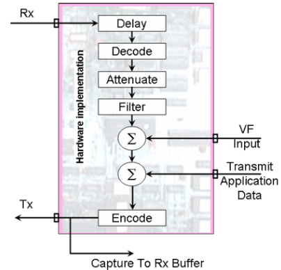
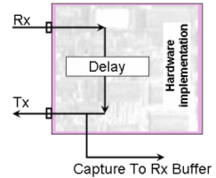
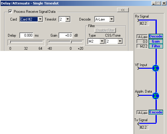
Applying delay, attenuation, and/or filtering to a received signal and retransmitting the processed signal on to the same receiving board Speech and/or noise may also be mixed in. The following diagram illustrates this configuration. - Applying pure delay to a signal: A received signal is delayed before being retransmitted. This configuration is illustrated in the figure below.
Interface
This section describes the operation of the controls in Delay/Attenuate - Single Timeslot Application.
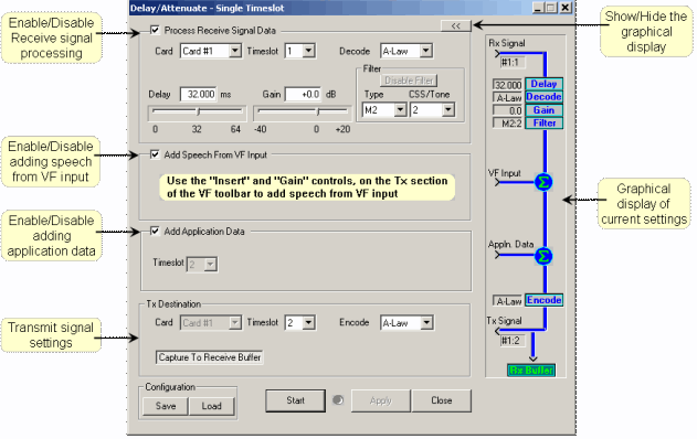
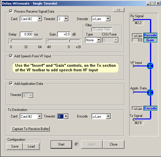
- Card, Timeslot, Encoding selection
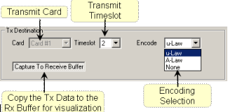
The user can select the Rx and Tx timeslots differently. In this application the receiving and transmitting cards must be the same. You can select the transmit timeslot different from the receive timeslot - Processing the received signal data
The following are the steps to process a received signal: - Select the card and timeslot using the card and timeslot controls
- Delay - Select a Delay value, appropriate for your testing. You can either type in a value or use the slider control to arrive at a specific value within the allowed range. The precision for Delay value is 0.125 milliseconds
- Decoding - Select a decoding scheme (A-Law, u-Law or None). If either A-Law or u-Law is selected you can specify the Gain value as well as the filter
- Gain - Select or enter a Gain value, which can have a granularity of 0.1 dB
- Filter - Select a filter type and signal type. The filter type can be M1 to M8 and the signal type can be 1 (CSS) or 2 (Tone). All together you can have 16 combinations of filter selection
- Filter and the Signal type as per ITU Specifications
Given below are the ITU specifications corresponding to the Filter type and the Signal type (CSS/Tone) selections. - Adding Speech from VF Input
You can add speech using VF input, and then transmit it through the transmit timeslot. You can also mix the VF input with the processed received signal and then transmit it - Adding Application Data
You can add the internally generated application data to the transmitted timeslot. Once you select the transmit timeslot, any internally generated data such as Tone, Gaussian noise etc on that particular timeslot will be added to the transmitted signal.
Intrusive Test > Transmit Tone or Intrusive Test > Transmit Gaussian Noise applications can be used to internally generate a signal, which will be transmitted on the same timeslot as in Delay Attenuation application.

Transmit encoding can be selected as A-Law, u-Law or none. If no decoding (None) is selected on the receive signal, the encoding will also become none.
The "Capture To Receive Buffer" toggle control will enable to capture the transmitted data to the receive buffer, which can be viewed using "Power Spectral" screen.
| SL.No | Filter Type | CSS/Tone | Scaling Factor | Minimum ERL for CSS/Tones (dB) |
| 1 | M1 | 1 (CSS) | 1.39 x 10⁻⁵ | 6 |
| 2 | M1 | 2 (Tone) | 1.22 x 10⁻⁵ | 6 |
| 3 | M2 | 1 (CSS) | 1.44 x 10⁻⁵ | 6.55 |
| 4 | M2 | 2 (Tone) | 6.78 x 10⁻⁶ | 6 |
| 5 | M3 | 1 (CSS) | 1.52 x 10⁻⁵ | 6 |
| 6 | M3 | 2 (Tone) | 9.66 x 10⁻⁶ | 6 |
| 7 | M4 | 1 (CSS) | 1.77 x 10⁻⁵ | 6 |
| 8 | M4 | 2 (Tone) | 1.07 x 10⁻⁵ | 6 |
| 9 | M5 | 1 (CSS) | 9.33 x 10⁻⁶ | 6 |
| 10 | M5 | 2 (Tone) | 7.05 x 10⁻⁶ | 6 |
| 11 | M6 | 1 (CSS) | 1.51 x 10⁻⁵ | 6 |
| 12 | M6 | 2 (Tone) | 8.60 x 10⁻⁶ | 6 |
| 13 | M7 | 1 (CSS) | 2.33 x 10⁻⁵ | 11.06 |
| 14 | M7 | 2 (Tone) | 6.58 x 10⁻⁶ | 6 |
| 15 | M8 | 1 (CSS) | 1.33 x 10⁻⁵ | 9.27 |
| 16 | M8 | 2 (Tone) | 4.58 x 10⁻⁶ | 6 |
The timeslot selected on the VF toolbar is not relevant as far as this application is concerned. For example if the transmit timeslot for this application is selected to be 2 and the VF input timeslot is selected as 5 then, on the transmitted T1/E1 signal, the timeslots 2 and 5 will contain the inserted VF signal. Depending on the other settings on this application, the transmitted signal on timeslot 2 will be summations of the processed receive signal and (or) the application data.

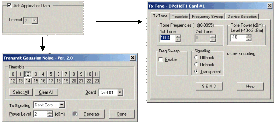
Once the configuration is complete, you can start the processing. Additionally if the graphical view is visible, it will show an animated display of the flow of data from the various input points to the output (transmit) point.

Resources
Note: PCs which include GL hardware/software require Intel or AMD processors for compliance.
Please Note: The XX in the Item No. refers to the hardware platform, listed at the bottom of the Buyer's Guide, which the software will be running on. PTA or PEA (tProbe Units), UTA or UEA (USB Units), HUT or HUE (Universal Cards), and HDT or HDE (HD cards) depending upon the hardware.
| Item No. | Item Description |
| XX062 | Echo Path Delay/Loss Simulation (Delay Attenuate Timeslots) Software (Not supported in T1E1 Quad and Octal boards) |
| Related Software | |
|---|---|
| XX020 | File Record/Playback Software |
| XX051 | Synchronous Trunk Record Playback |
| XX022 | Dial DTMF/MF Digits Software (optional) |
| XX031 | Enhanced T1 / E1 Call Capture/Analysis Software (optional) |
| XX063 | Echo Path Delay/Loss Measurement Software |
| XX065 | G.168 Echo Canceller Test Suite |
| XX066 | Digital Echo Canceller |
| XX067 | Automated Echo Canceller Testing with or without VQT |
| XX068 | Semi-automated Scripted EC Testing |
| Related Hardware | |
| HDT001/HDE001 | Legacy HD T1 or E1 (PCI) Cards with Basic Analyzer Software |
| UTE001 | Portable USB based Dual T1 or E1 Laptop Analyzer |
