T3 E3 ultra-high-speed signal Analyzer for Channelized & Unchannelized Solutions
T3 line is a high-speed signal capable of transmitting data at 44.736 Mbps, structured into 28 T1 channels or used unstructured for data. An E3 line at 34.368 Mbps can be organized into 16 E1 channels or used unstructured for versatile data transmission.
Request a Demo / Quote Brochure
T3 E3 - ultra-high-speed signal
A T3 line is an ultra-high-speed signal capable of transmitting data at rates up to 44.736 Mbps. An E3 signal is situated at the third level within the Plesiochronous Digital Hierarchy (PDH) and has a bit rate of 34.368 Mbps.
T3 or E3 has two flavours channelized (structured) and unchannelized (unstructured).
- In Channelized (Structured), a T3 (DS3) consists of 7 T2s (DS2) and each T2 consists of 4 T1s (DS1), thus a total of 28 T1s, or 672 full duplex voice channels are provided. Similarly, an E3 consists of 4 E2s and each E2 consists of 4 E1s, thus a total of 16 E1s, or 480 full duplex voice channels are provided. Thus, a channelized T3 signal carries 28 T1 signals, each operating at a rate of 1.544 Mbps. A channelized E3 signal carries 16 E1 signals each operating at a rate of 2.048 Mbps
- In Unchannelized (Unstructured), T2s or T1s or E2s or E1s DO NOT exist within T3 or E3. Instead, most of the capacity within 44.736 Mbps for T3 and 34.368 Mbps for E3 is used for data, with a small amount for overhead. With the advent of the internet, T3 (DS3) and E3 can be used to transport not only data, but also packetized voice, and packetized video. Example protocols include Asynchronous Transfer Mode (ATM), PPP, HDLC, and Frame Relay
Overview
GL’s T3 E3 Analyzer is available as portable as well as in mTOP™ hardware variations. GL offers both high density rackmount system and all-in-one standalone portable unit.
- A portable USB-based unit supports 2x T3 E3 ports per unit
- A 2U Rack supports 6x T3 E3 ports (6 X 672 DS0s) per unit. Multiple rack units can be stacked together for greater scalability
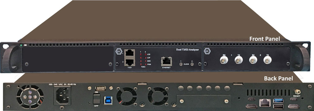
- An mTop™ 1U rack can support 4 T3 E3 ports (2 X 672 DS0s)
- Portable mTOP™ Probe unit along with a single T3 E3 USB hardware unit includes pc interface, making it suitable for field testing

1U mTOP™ Rack T3 E3 Analyzer
Portable USB T3 E3 Analyzer
mTOP™ Probe T3 E3 Analyzer
The T3 E3 Analysis software compliments the hardware and supports simultaneously monitoring up to 12 x T3 E3 lines (2x 2U Rack PC or 6x Portable units) for all alarms, frame errors, signaling and data. If one adds the Channelized T1 Analyzer software to the system, then the T1s within the T3s can also be analyzed in software, 12 x T3 E3 lines (=12*28 T1s) constituting 336 full duplex T1s, or 672 simplex T1s monitored simultaneously using a single mTOP™ Rack unit. With additional applications, such as record-only, one can also record traffic at DS0 levels.
GL’s T3 E3 Analyzer is capable of processing signaling, voice, and data full T3 (DS3) or E3 data streams, dropping and inserting T1 (DS1) or E1, and analysis of HDLC, ATM, Frame Relay, and PPP Protocols. It includes various signal testing capabilities for Unchannelized (Unstructured) and Channelized (Structured) T3 E3 Traffic.
GL also offers mTOP™ Probe T3 E3 variant which includes the USB based T3 E3 Analyzer hardware unit combined with necessary PC interface (Intel i3/i7, 256GB HDD, 8GB memory, Win10 Pro 64 bit) within a single box, making it portable stand-alone tester suitable for field testing.
The channelized option in the T3 E3 Analyzer uses “software-only” approach to support direct access to all 2x28 T1s or 2x21 E1s or 2x16 E1s on a T3 E3 line per board for analysis and monitoring– all within a single PC, including differing T1 E1 framing formats, physical layer alarms, and payloads.
GL's T3 E3 Analyzer also includes scrambling and subrate features. Subrate allows fractional bandwidth, i.e. less than the full 44.736 Mbps. Scrambling improves synchronization performance by randomizing repetitive patterns and long strings of zeros.
- Analysis/Emulation of T3 (44.736 Mbps) and E3 (34.368 Mbps)
- Analysis/Emulation of ATM, PPP, HDLC, and Frame Relay signaling
- Record/Playback of entire T3 or E3
- Monitoring & generating alarms, and error insertion
- Analysis of all 28 T1s (1.544 Mbps each) per T3 port, or 16 E1s (2.048 Mbps each) per E3 port in Channelized mode
- Analysis of Fractional T1s and E1s, N x T1s or N x E1s
- Analysis of any combination of DS0s (64 kbps each) within the T1s or E1s ( for example, each T3 port has 28 x 24 = 670 DS0s for T1 or 21 x 32 = 672 DS0s for E1)
Features
- One of the smallest and lightest T3 (DS3) /E3 analysis platforms with dual data stream capture capability
- Multiple interfaces for analysis (T3 (DS3) /E3, T1 E1 and Ethernet) and control (USB and Ethernet) to support a wide array of testing scenarios
- Plug and Play through USB 2.0 control interface
- Software Selectable T3 (DS3) and E3 interface along with T1 and E1 Drop and Insert
- Dual T3 (DS3) /E3 Receivers and Transmitters for non-intrusive and intrusive testing of both eastbound and westbound signals at the same time
- Channelized (Structured) Testing
With Drop and Insert Functionality –
- Uses the Dual T1 E1 ports on the hardware
- Multiplex/De-multiplex T1 (DS1) /E1 signals (Drop and Insert)
- Receivers for bidirectional monitoring with Dual T1 (DS1)/E1 drop
- Transmit multiplexed externally inserted or internally generated T1 E1 streams into T3 (DS3)/E3
- Stress test M13 (E13) multiplexers and 3/1 Digital cross connect systems
- Dual channel drop and insert of T1 E1 signals from any one of the T3 (DS3) /E3 signals
- Broadcast or Loopback Individual T1s/E1s received from T3 (DS3) /E3
With T1 E1 Tx/Rx Server Software –
- T1 E1 frames are transmitted by the T1 E1 Transmit Server over T3 E3 line
- T3 E3 Data is received by the T1 E1 Receive Server, which demultiplexes the data to T1 or E1 Channels
- Send/Receive 28 T1 Channels per port from T3 signal
- Receive 21 E1 Channels per port (G.747 Mapping) per port from T3 signal
- Receive 16 E1 Channels per port from E3 signal
- Supports monitoring of framed and unframed T1 E1 (Rx Only)
- Simultaneous analysis of all 56 T1s (1.544 Mbps each), or 32 E1s (2.048 Mbps each)
- Analysis of Fractional T1s and E1s, N x T1s or N x E1s
- Analysis of any combination of DS0s (64 kbps each) within the T1s or E1s, 56 x 24 = 1,344 DS0s for T1 or 32 x 32 = 1024 DS0s
- Supports Protocol Analysis of all structured protocols – HDLC, ISDN, CAS, and many more
- Monitoring of T1 E1 Alarms, Payload, an d Framing structure
- Unchannelized (Unstructured) Testing
- WAN Testing
- Analysis and simulation of ATM, PPP, HDLC, and Frame Relay protocols
- Transmit/Verify HDLC frames with user defined headers
- supports scrambling and subrate for the following DSU vendors' algorithms for T3 interface: Digital Link, Larscom, Verilink, and Adtran
- BIT Error Rate Test (BERT)
- Perform BERT on T3 E3 channels simultaneously
- Enhanced to support BERT through Windows Client Server Commands (WCS)
- Flexible clocking - internal, recovered (from T3 E3, T1 or E1) and external
- Scripting and Automation through GL’s well-known Windows Client Server (WCS) approach
- WCS clients are available for Windows® and Linux® operating system via console/terminal Command Line Interface and accessible remotely through SSH
- WCS commands can be issued in Python scripts running in Windows or Linux
- Includes HDL File Conversation utility to convert ethereal format file (*.PCAP, *.CAP, and *.PCAPNG) to GL’s file format (*.HDL) and vice-versa
- Monitor/Manage the Analyzer remotely via Ethernet port (future enhancement)
Portable Test Solution for TDM, SDH, Packet, and Analog
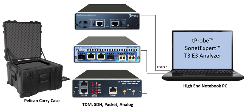
Solution : tProbe™ + SonetExpert™ + T3/E3 Analyzer
Rackmount T3 E3 Specifications
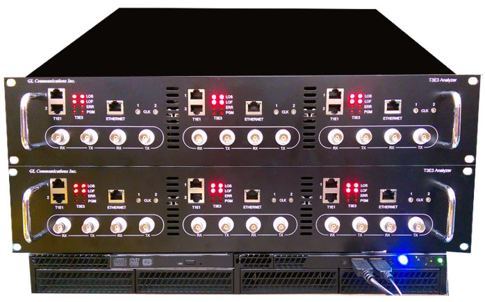
2U Rackmount T3 E3 Analyzer |
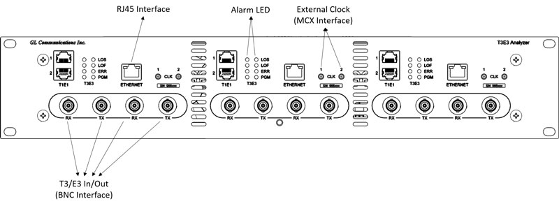 Rackmount T3 E3 Front Panel |
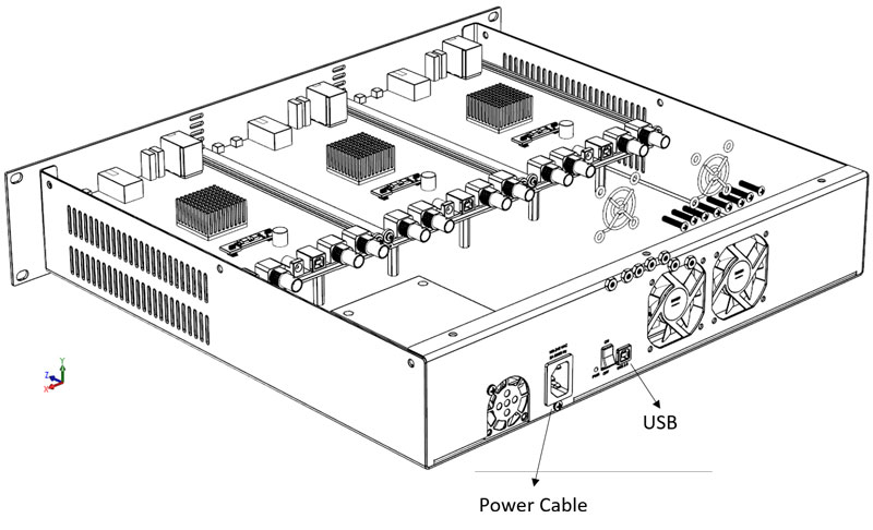
Rackmount T3 E3 Rear Panel |
| Connectors for Rack T3 E3 |
|
|---|---|
T3 (DS3)/E3 |
Up to 6 Pairs of DS3/E3 75O BNC (Tx, Rx) Ports |
T1 (DS1) /E1 |
Up to 6 Pairs of DS1/E1 RJ-48-c (Tx, Rx) for Drop/Insert |
External Clock |
6x MCX External Clock Ports |
PC Interface |
3x USB 2.0 Connected to a USB HUB |
External Power |
Internally powered by Power Supply |
Ethernet |
3 x 1000 Mbps Ethernet Port |
| T3 (DS3)/E3 Line Interface | |
|---|---|
Output Amplitude |
800mV ± 50mV |
Input Impedance |
75 Ohms unbalanced (BNC) |
Line Code |
B3ZS (T3), HDB3 (E3) |
Terminate Input Level |
0.09Vp – 0.85Vp |
Monitor Input Level |
0.025Vp – 0.08Vp |
| Clock Source | |
|---|---|
Internal |
± 1 PPM @25C [± 4.5 ppm (includes ageing, stability)] |
Recovered |
Clock recovered from receiver |
External |
TTL Level signal |
| T3 (DS3)/E3 Transmitter | |
|---|---|
T3 (DS3)/E3 Payloads |
Framed T3 (DS3)/E3 Data, Unframed T3 (DS3)/E3, Idle, AIS |
T3 Framing Modes |
Unframed M13 (ANSI T1-107 – 1995) Structured (Channelized), and Unstructured (Unchannelized) C-bit (ANSI T1-107 – 1990) - Structured (Channelized), and Unstructured (Unchannelized) Unchannelized T3 supports subrate and scrambling formats for Digital Link, ADC/Kentrox, Larscom, Adtran, and Verilink data service units (DSUs) |
E3 Framing Modes |
Unframed, E13 (for E3) - Structured (Channelized), and Unstructured (Unchannelized) |
Framed T3 (DS3)/E3 Unstructured Payload |
Raw Data from File, ATM Cells (only for T3), HDLC Frames, BERT Patterns |
Unframed E3 Payload |
Raw Data from File, BERT Patters |
Channel Structure |
T1, E1 (DS1) (ITU-T G.747) |
BERT Patterns |
QRSS, 26-1, 29-1, 211-1, 215-1, 220-1, 223-1, User Defined up to 32-bits, other static patterns |
T1 (DS1) Payload |
Inserted T1, AIS, Loopback, BERT Patterns (future) |
E1 Payload |
Inserted E1, AIS, Loopback, BERT Patterns (future) |
Loopbacks |
Complete T3 (DS3)/E3 Signal, Selected T1s/E1s from incoming T3 (DS3)/E3 |
| T3 (DS3)/E3 Receiver | |
|---|---|
T3 (DS3) Framing Format |
M13 (ANSI T1-107 – 1995), C-bit (ANSI T1-107 – 1990), Unframed, Structured (Channelized), and Unstructured (Unchannelized) |
E3 Framing Format |
E13, Unframed, Structured (Channelized), and Unstructured (Unchannelized) |
Channel Structure |
T1 (DS1) /E1 (ITU-T G.747) |
Framed T3 (DS3)/E3 Unstructured Payload |
Raw Data Captured to File, ATM Analysis (only for T3), HDLC Frames Analysis, BERT Patterns Measurement |
Framed T3 (DS3)/E3 Structured Payload |
Raw Data Captured to File, BERT Patterns Measurement, Drop Selected T1(s)/E1(s) |
| T1 E1 Transmit/Receiver: | |
|---|---|
|
Bit error rate testing (BERT) pattern generation and detection per channel |
|
Transmit Tone, Transmit Gaussian Noise, Transmit Multiframe |
|
Transmit Signaling Bits, and Rx-to-Tx loopback |
Compliance |
G.703 Physical/Electrical Characteristics |
| Supported Protocols | |
|---|---|
Channelized Protocols |
High-Level Data Link Control (HDLC) |
UnChannelized Protocols (Unstructured) |
PPP, ATM, Frame Relay |
| Miscellaneous | |
|---|---|
T3 (DS3)/E3 Line Rate Offset |
± 50 PPM in 1 ppm Steps |
Level Measurement |
Supported |
Frequency Measurement |
± 1 PPM |
T3 (DS3) Error Add |
Payload Bit, Frame Errors, P-bit, C-bit, EXZ (for T3); |
E3 Error Add |
Frame Errors, Code Violation (CV) Error, EXZ, Payload Bit |
T3 (DS3) Alarm Generation |
LOS, AIS, RAI (X-bit), Idle, FEAC Codes (Loopback and alarm/status codes) |
T3 (DS3) Alarm Monitoring |
LOS, LOF, AIS, Idle, RAI (X-bit), EXZ |
E3 Alarm Generation |
LOS, OOF, RAI (X-bit); |
E3 Alarm Monitoring |
LOS, LOF, AIS, RAI (X-bit), EXZ |
T3 (DS3) FEAC Codes |
Alarm status codes, loopback codes with channel indicator for T1 |
LED Indicators |
LOS, LOF, ERR, PGM |
| Mechanical | |
|---|---|
Dimensions |
18.920 (width), 16.075 inch (depth), 3.390 inch (height) |
Weight |
est. 20 lbs |
Power Supply |
100-240V, 5A, 50/60Hz |
Operating temperature |
0° C to 40 ° C |
Storage temperature |
10° C to 70 ° C |
Relative humidity |
10 % min, 90 % max, non-condensing |
| Functional Specifications |
|---|
| DS3/E3 multiplexing from T1 E1 |
| DS3/E3 Playback and Capture |
| DS3/E3 Protocol Analysis |
| DS3/E3 Bert Analysis |
| Sending DS3/DS1 SNMP Traps to Network Operation Center (NOC) |
| T3 E3 Signal |
|---|
| Up to 168 T1 per unit (or 3*2* 28) |
| Up to 126 E1 per port (or 3*2* 21) |
| For E3 Signal - Up to 96 E1 (or 3*2* 16) |
* Specifications subject to change without notice.
Portable USB T3 E3 Specifications
World’s smallest T3 (DS3) /E3 Analysis platform with dual data stream capture capability:
With the size of a small paperback book and weighing only 1.75 lbs, GL's newest T3 E3 Analyzer pod is one of the smallest and lightest analyzer units in the world. The small footprint makes it ideal for use in the lab as well as in the field. The unit's lightweight makes it easy to carry in the pouch of a Notebook PC making it perfect for air travel. Compatibility with any Desktop or Notebook PC allows the software to be installed on many PCs - just ship the unit to the intended location and use it on an available PC.
Multiple interfaces for analysis (T3 E3) and control (USB, Ethernet) makes it ideal for a wide array of testing scenarios:
- T3 (DS3) or E3 - BNC interface (2 Transmit and 2 Receive ports)
- T1 or E1 - RJ-48c interface (2 Transmit/Receive Ports)
- External Clock: MCX (2 Ports – one each for the two T3 E3 ports)
- Ethernet Port – For wirespeed Ethernet analysis, remote monitoring, and management
- USB 2.0 - The USB interface is used to connect the analyzer unit to a Desktop or a Notebook PC for storage, display, and control
Plug and play through the USB 2.0 control interface:
Its USB 2.0 control interface to PC enables plug and play capability. This will allow you to share the unit among multiple users since it can be moved from PC to PC. The unit is also highly portable due to the small size and light weight.
Comprehensive T3 E3 testing solution:
GL’s T3 E3 analyzer unit offers a complete solution for T3 E3 (44.736/34.368 Mbps) testing. It is fully compatible with GL’s other test systems. It can be used in conjunction with GL’s Laptop T1 E1 analyzer for individual T1, E1, DS0, and analog analysis.
| Connectors | |
|---|---|
T3 (DS3)/E3 |
2x DS3/E3 75Ω BNC (Tx, Rx) Ports |
T1 (DS1) /E1 |
2x DS1/E1 RJ-48c (Tx, Rx) for Drop/Insert |
External Clock |
2x MCX External Clock Ports |
PC Interface |
1x USB 2.0 for PC Interface |
External Power |
12 Volts (Medical Grade), 3 Amps |
Ethernet |
1x 1000 Mbps Ethernet Port |
| T3 (DS3)/E3 Line Interface | |
|---|---|
Output Amplitude |
800mV ± 50mV |
Input Impedance |
75 Ohms unbalanced (BNC) |
Line Code |
B3ZS (T3), HDB3 (E3) |
Terminate Input Level |
0.09Vp – 0.85Vp |
Monitor Input Level |
0.025Vp – 0.08Vp |
| Clock Source | |
|---|---|
Internal |
± 1 PPM @25C [± 4.5 ppm (includes ageing, stability)] |
Recovered |
Clock recovered from receiver |
External |
TTL Level signal |
| T3 (DS3)/E3 Transmitter | |
|---|---|
T3 (DS3)/E3 Payloads |
Framed T3 (DS3)/E3 Data, Unframed T3 (DS3)/E3, Idle, AIS |
T3 Framing Modes |
Unframed M13 (ANSI T1-107 – 1995) Structured (Channelized), and Unstructured (Unchannelized) C-bit (ANSI T1-107 – 1990) - Structured (Channelized), and Unstructured (Unchannelized) Unchannelized T3 supports subrate and scrambling formats for Digital Link, ADC/Kentrox, Larscom, Adtran, and Verilink data service units (DSUs) |
E3 Framing Modes |
Unframed, E13 (for E3) - Structured (Channelized), and Unstructured (Unchannelized) |
Framed T3 (DS3)/E3 Unstructured Payload |
Raw Data from File, ATM Cells (only for T3), HDLC Frames, BERT Patterns |
Unframed E3 Payload |
Raw Data from File, BERT Patters |
Channel Structure |
T1, E1 (DS1) (ITU-T G.747) |
BERT Patterns |
QRSS, 26-1, 29-1, 211-1, 215-1, 220-1, 223-1, User Defined up to 32-bits, other static patterns |
T1 (DS1) Payload |
Inserted T1, AIS, Loopback, BERT Patterns (future) |
E1 Payload |
Inserted E1, AIS, Loopback, BERT Patterns (future) |
Loopbacks |
Complete T3 (DS3)/E3 Signal, Selected T1s E1s from incoming T3 (DS3)/E3 |
| T3 (DS3)/E3 Receiver | |
|---|---|
T3 (DS3) Framing Format |
M13 (ANSI T1-107 – 1995), C-bit (ANSI T1-107 – 1990), Unframed, Structured (Channelized), and Unstructured (Unchannelized) |
E3 Framing Format |
E13, Unframed, Structured (Channelized), and Unstructured (Unchannelized) |
Channel Structure |
T1 (DS1) /E1 (ITU-T G.747) |
Framed T3 (DS3)/E3 Unstructured Payload |
Raw Data Captured to File, ATM Analysis (only for T3), HDLC Frames Analysis, BERT Patterns Measurement |
Framed T3 (DS3)/E3 Structured Payload |
Raw Data Captured to File, BERT Patterns Measurement, Drop Selected T1(s) E1(s) |
| T1 E1 Transmit/Receiver: | |
|---|---|
|
Bit error rate testing (BERT) pattern generation and detection per channel |
|
Transmit Tone, Transmit Gaussian Noise, Transmit Multiframe |
|
Transmit Signaling Bits, and Rx-to-Tx loopback |
Compliance |
G.703 Physical/Electrical Characteristics |
| Supported Protocols | |
|---|---|
Channelized Protocols |
High-Level Data Link Control (HDLC) |
UnChannelized Protocols (Unstructured) |
PPP, ATM, Frame Relay |
| Miscellaneous | |
|---|---|
T3 (DS3)/E3 Line Rate Offset |
± 50 PPM in 1 ppm Steps |
Level Measurement |
Supported |
Frequency Measurement |
± 1 PPM |
T3 (DS3) Error Add |
Payload Bit, Frame Errors, P-bit, C-bit, EXZ (for T3); |
E3 Error Add |
Frame Errors, Code Violation (CV) Error, EXZ, Payload Bit |
T3 (DS3) Alarm Generation |
LOS, AIS, RAI (X-bit), Idle, FEAC Codes (Loopback and alarm/status codes) |
T3 (DS3) Alarm Monitoring |
LOS, LOF, AIS, Idle, RAI (X-bit), EXZ |
E3 Alarm Generation |
LOS, OOF, RAI (X-bit); |
E3 Alarm Monitoring |
LOS, LOF, AIS, RAI (X-bit), EXZ |
T3 (DS3) FEAC Codes |
Alarm status codes, loopback codes with channel indicator for T1 |
LED Indicators |
LOS, LOF, ERR, PGM |
| Mechanical | |
|---|---|
Dimensions |
1.6" high, 9.25" deep, 5.5" wide |
Weight |
1.75 lbs |
Power Supply |
Input 9 V DC at 1 A |
Operating temperature |
0° C to 40 ° C |
Storage temperature |
10° C to 70 ° C |
Relative humidity |
10 % min, 90 % max, non-condensing |
| Functional Specifications |
|---|
| DS3/E3 multiplexing from T1 E1 |
| DS3/E3 Playback and Capture |
| DS3/E3 Protocol Analysis |
| DS3/E3 Bert Analysis |
| Sending DS3/DS1 SNMP Traps to Network Operation Center (NOC) |
| T3 E3 Signal |
|---|
| Up to 56 T1 per unit (or 2* 28) |
| Up to 42 E1 per port (or 2* 21) |
| For E3 Signal - Up to 32 E1 (or 2* 16) |
* Specifications subject to change without notice.
1U mTOP™ Rack Solutions - T1 E1, and T3 E3
GL’s mTOP™ rack based Channelized/unchannelized T3 E3 Analyzer, supports T3 E3 and T1 E1 Multi-interface. A T3 (DS3) consists of a total of 28 T1s, or 672 full duplex voice channels. Similarly, an E3 consists of a total of 16 E1s, or 480 full duplex voice channels.
Almost all of GL’s T1 E1 Testers can be accommodated into rack-based units.
Stacked 1U mTOP™ Rack T3 E3 Analyzer
| Space Requirements |
|---|
|
| Embedded PC Specifications |
|
| Connectors for T3 E3 |
|
mTOP™ T3 E3 Specifications
T3 E3 Specifications
| T3 (DS3)/E3 Line Interface | |
|---|---|
Output Amplitude |
800mV ± 50mV |
Input Impedance |
75 Ohms unbalanced (BNC) |
Line Code |
B3ZS (T3), HDB3 (E3) |
Terminate Input Level |
0.09Vp – 0.85Vp |
Monitor Input Level |
0.025Vp – 0.08Vp |
| Clock Source | |
|---|---|
Internal |
± 1 PPM @25C [± 4.5 ppm (includes ageing, stability)] |
Recovered |
Clock recovered from receiver |
External |
TTL Level signal |
| T3 (DS3)/E3 Transmitter | |
|---|---|
T3 (DS3)/E3 Payloads |
Framed T3 (DS3)/E3 Data, Unframed T3 (DS3)/E3, Idle, AIS |
T3 Framing Modes |
Unframed M13 (ANSI T1-107 – 1995) Structured (Channelized), and Unstructured (Unchannelized) C-bit (ANSI T1-107 – 1990) - Structured (Channelized), and Unstructured (Unchannelized) Unchannelized T3 supports subrate and scrambling formats for Digital Link, ADC/Kentrox, Larscom, Adtran, and Verilink data service units (DSUs) |
E3 Framing Modes |
Unframed, E13 (for E3) - Structured (Channelized), and Unstructured (Unchannelized) |
Framed T3 (DS3)/E3 Unstructured Payload |
Raw Data from File, ATM Cells (only for T3), HDLC Frames, BERT Patterns |
Unframed E3 Payload |
Raw Data from File, BERT Patters |
Channel Structure |
T1, E1 (DS1) (ITU-T G.747) |
BERT Patterns |
QRSS, 2^6-1, 2^9-1, 2^11-1, 2^15-1, 2^20-1, 2^23-1, User Defined up to 32-bits, other static patterns |
T1 (DS1) Payload |
Inserted T1, AIS, Loopback, BERT Patterns (future) |
E1 Payload |
Inserted E1, AIS, Loopback, BERT Patterns (future) |
Loopbacks |
Complete T3 (DS3)/E3 Signal, Selected T1s E1s from incoming T3 (DS3)/E3 |
| T3 (DS3)/E3 Receiver | |
|---|---|
T3 (DS3) Framing Format |
M13 (ANSI T1-107 – 1995), C-bit (ANSI T1-107 – 1990), Unframed, Structured (Channelized), and Unstructured (Unchannelized) |
E3 Framing Format |
E13, Unframed, Structured (Channelized), and Unstructured (Unchannelized) |
Channel Structure |
T1 (DS1) /E1 (ITU-T G.747) |
Framed T3 (DS3)/E3 Unstructured Payload |
Raw Data Captured to File, ATM Analysis (only for T3), HDLC Frames Analysis, BERT Patterns Measurement |
Framed T3 (DS3)/E3 Structured Payload |
Raw Data Captured to File, BERT Patterns Measurement, Drop Selected T1(s) E1(s) |
| T1 E1 Transmit/Receiver | |
|---|---|
|
Bit error rate testing (BERT) pattern generation and detection per channel |
|
Transmit Tone, Transmit Gaussian Noise, Transmit Multiframe |
|
Transmit Signaling Bits, and Rx-to-Tx loopback |
Compliance |
G.703 Physical/Electrical Characteristics |
| Supported Protocols | |
|---|---|
Channelized Protocols |
High-Level Data Link Control (HDLC) |
UnChannelized Protocols (Unstructured) |
PPP, ATM, Frame Relay |
| Miscellaneous | |
|---|---|
T3 (DS3)/E3 Line Rate Offset |
± 50 PPM in 1 ppm Steps |
Level Measurement |
Supported |
Frequency Measurement |
± 1 PPM |
T3 (DS3) Error Add |
Payload Bit, Frame Errors, P-bit, C-bit, EXZ (for T3); |
E3 Error Add |
Frame Errors, Code Violation (CV) Error, EXZ, Payload Bit |
T3 (DS3) Alarm Generation |
LOS, AIS, RAI (X-bit), Idle, FEAC Codes (Loopback and alarm/status codes) |
T3 (DS3) Alarm Monitoring |
LOS, LOF, AIS, Idle, RAI (X-bit), EXZ |
E3 Alarm Generation |
LOS, OOF, RAI (X-bit); |
E3 Alarm Monitoring |
LOS, LOF, AIS, RAI (X-bit), EXZ |
T3 (DS3) FEAC Codes |
Alarm status codes, loopback codes with channel indicator for T1 |
LED Indicators |
LOS, LOF, ERR, PGM |
| Functional Specifications |
|---|
| DS3/E3 multiplexing from T1 E1 |
| DS3/E3 Playback and Capture |
| DS3/E3 Protocol Analysis |
| DS3/E3 Bert Analysis |
| Sending DS3/DS1 SNMP Traps to Network Operation Center (NOC) |
| T3 E3 Signal |
|---|
| Up to 56 T1s per T3 unit (or 1*2* 28) Up to 42 E1s per T3 unit (or 1*2* 21) Up to 32 E1s per E3 unit (or 1*2* 16) |
* Specifications subject to change without notice.
mTOP™ T1 E1 Specifications
T1 E1 Specifications
| Physical Interface | |
|---|---|
USB Connector |
(1) USB TYPE B Jack |
Ethernet Connector |
(1) RJ-45 10/100 Ethernet Jack |
T1 E1 Connectors |
(2) RJ-48c Jacks |
Audio Connectors |
(4) 3.5 mm Balanced (Stereo) or unbalanced (Mono) Audio Jacks (TX & RX) |
External Clock Connector |
(1) MCX Coaxial Jack |
External Power Connector |
(1) Coaxial DC Power Jack (mates with 5.5mm x 2.1mm coaxial plug) |
| Optional Boards | |
|---|---|
2-Wire Daughter Board (One FXO, One FXS) |
FXO - RJ-11 |
Datacom Daughter Board |
Dual DB25 Connectors Support: |
| External Power Requirements | |
|---|---|
Power Adapter Requirements |
+5V @ 2A Max Power to the Center Ring |
| T1 E1 Line Interface | |
|---|---|
Framing Formats |
Unframed, D4 (T1) , ESF(T1), CAS(E1), FAS(E1), CRC4 |
Line Code format |
AMI, B8ZS (T1) or HDB3 (E1) |
Internal Clock Specification |
Standard: ± 3ppm Optional: ± 1ppm |
Output Clock Source |
Internal (± 1 ppm or 3 ppm), Recovered, External Clock |
T1 Output Level |
T1: 3.0V Base to Peak Selectable 0-655Ft Pulse Equalization Setting; Tx Capability - DSX-1 Outputs (to 655 feet) |
E1 Output Level |
E1: 3.0V ± 0.3V Base to Peak |
Input Level |
75 mV to 6V base to peak or -30 dBsx to -6 dBsx |
Line Built Out Selections |
0dB, -7.5dB, -15dB, -22.5dB for T1 only |
Loopback |
Normal (Outward and Inward) |
| Transmit | |
|---|---|
T1 E1 Interface Hardware Compliance |
- ANSI: T1.403.1995, T1.231-1993, T1.408 |
BERT Pattern Generation |
Pseudorandom patterns: (63) 26-1, (511) 29-1,
(2047) 211-1, (32767) 215-1, (1048575) 220-1, (8388607) 223-1,
QRSS. |
Alarm Insertion |
Blue, Yellow, Remote, Distant Multiframe |
Error Insertion |
BPV, Bit Error, Frame Error, CRC Errors, Burst Frames, Fixed Error Rate, Random Error Rate, auto logic from 10-2 to 10-9 for selectable 56K or 64Kps channels. |
Drop and Insert |
Any contiguous set of digital timeslots and/or audio input |
Facility Data Link |
T1 ESF Mode: Transmit/Receive Messages, Bit-Oriented Messages, and Files. |
Zero Suppression |
B7 Stuffing, Transparent, & B8ZS (T1) |
Signaling |
Robbed-Bit or Clear Channel |
Frequency Offset |
T1: +/- 615Hz E1: +/- 615Hz |
| Receive | |
|---|---|
Input Impedance |
100 ohms for Terminate and Monitor (T1) |
Terminations |
Terminate, Monitor, Bridge |
T1 Input Frequency |
1.544MHz ± 20KHz |
E1 Input Frequency |
2.048Mhz ± 20KHz |
Frequency Measurement |
± 1ppm |
Error Detection |
Frame Error, CRC Error, BPV Error, Logic Error, Frame Alignment Error |
Alarm Detection |
T1 - D4 Yellow Alarm, ESF Yellow Alarm |
Intrinsic Jitter |
Meets Jitter Tolerance: |
Input Range |
T1: Terminate, 0 to 36dB (Long Haul), DSX Monitor, Bridge |
| Display and Logging | |
|---|---|
BERT |
Bit Errors, Bit Error Rate, Error Seconds, Error Free Seconds, %EFS, Severely Error Seconds, % SES, Degraded Minutes, %Dmin, Loss Pattern Sync Count, Loss of Sync Seconds, Available Seconds, %Available Seconds, Unavailable Seconds, Bipolar Violations, BPV Rate, BPV Seconds, BPV Free Seconds, Frame Errors, FE Rate, FE Seconds, FE Free Seconds, with Detailed logging into disk file. |
Alarms |
Resync In Progress, Loss of Signal, Blue Alarm, Change of Frame Alignment, Bipolar Violation, Frame Error, Carrier Loss, Yellow Alarm, Out of Frame Events Counter, Error Super frame Counter, Bipolar Violations, Remote Alarm, Distant Multiframe Alarm, Signaling All Ones, CAS Multiframe Error, CRC4 Error. |
| VF Drop and Insert | |
|---|---|
| Refer to VF Drop and Insert Capabilities webpage for more details. | |
Rx Termination |
High Impedance (>50K Ohms) for Non-Intrusive Testing |
Tx Termination |
135, 150, 600, 900 Ohms |
Sampling Rates |
8KHz |
Datawidth (bits) |
Supports 8, 16, 20, 24, 32 Bit Data |
VF Tx Gains |
Supports -12 dB to +59 dB in 0.5dB Steps Gain (0.1 dB steps can also be accommodated in tProbe™) |
VF Rx Gains |
Supports -63.5 dB to +9 dB in 0.5dB Steps Attenuation (0.1 dB steps can also be accommodated in tProbe™) |
Connectors |
(4) 3.5 mm Balanced (Stereo) or Unbalanced (Mono) Audio Jacks (TX & RX) |
* Specifications subject to change without notice.
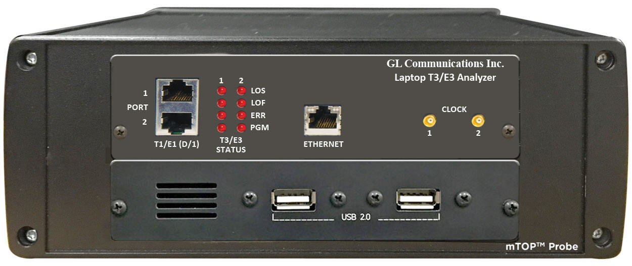
mTOP™ Probe T3 E3
mTOP™ Probe T3 E3 unit includes GL’s USB based T3 E3 Analyzer hardware unit combined with necessary PC interface, which makes it portable stand-alone unit suitable for field testing. A single portable USB-based unit supports 2x T3 E3 ports per unit.
GL’s T3 E3 Analyzer is capable of processing signaling, voice, and data full T3 (DS3) or E3 data streams, dropping and inserting T1 (DS1) or E1, and analysis of HDLC, ATM, Frame Relay, and PPP Protocols. It includes various signal testing capabilities for Unchannelized (Unstructured) and Channelized (Structured) T3 E3 Traffic. Shown below is a Probe based T3 E3 Analyzer unit.
T3 E3 Multi Interface mTOP™ Solution Brochure
|
mTOP™ Probe T3 E3 Analyzer 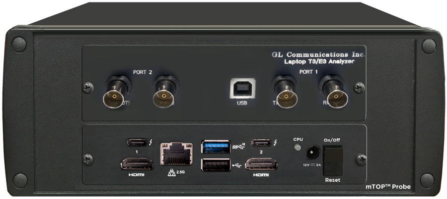
mTOP™ Probe T3 E3 Analyzer |
Refer to T3 E3 Price List |
Physical Layer Analysis
Physical Layer Analysis is used to monitor T3 E3 and T1 E1 line alarms. The analyzer helps to track the time at which alarms (Sync Loss, Carrier Loss, Remote, Distance MF, AIS) occurrs and periodically send these information to either centralized database such as Oracle DB, or send traps to SNMP monitoring applications.
GL’s NetSurveryorWeb™ accesses fetches the records from the central database and facilitates the user to monitor physical layer status of T1 E1 line via simple web based clients. For more details, refer to Network Line Monitor and Test
Features
- Captures LOS, LOF, AIS, IDLE, RAI/X-BIT, Excessive 0’s alarms at T3 E3 level
- Captures Sync Loss, Carrier Loss, AIS, Blue, Yellow, Distance MF, Frame Error alarms at T1 E1 level
- SNMP traps can be sent to SNMP notification receiving applications, like OpenView according to DS1-MIB (RFC 4805) and DS3-MIB (RFC 3896)
- Alarms can be captured for a specified time interval
- Advanced filtering and search based on any user selected alarms
- Displays Summary, Detail, Hex-Dump, and Statistics views
- Exports Summary and Detail View information’s to an ASCII file
- Provides options to save captured alarms into an HDL file and these files can be imported offline for further analysis
- Channelized T3 E3 application can monitor Physical Layer Alarms up to 336 ports
- USB T3 E3 application can monitor Physical Layer Alarms up to 12 ports
Supported T1 E1 Alarms
Line Sync Loss: This alarm indication will flash when a receiver resync is in progress. If the receiver is set to auto resync in the Configuration Menu, the receiver will begin resync when an OOF (Out Of Frame) event or Loss of Carrier is detected.
Carrier Loss: Carrier loss alarm is declared when 128 ± 1 consecutive zero's are detected. Carrier loss clears when a ‘1’ is received.
Remote Alarm Detected (E1 Only): This alarm indication will flash when a remote alarm is detected. A remote alarm is defined as the reception of three consecutive bits equal to ‘1’ of timeslot 0 of non-align frames.
Distant Multiframe (MF) (E1 Only): This alarm indication will flash when a distant multiframe alarm is detected. A distant multiframe alarm is defined as the reception of three consecutive 1s at bit position of timeslot 16 in frame 0. This indication is only valid when in CAS mode.
Alarm Indication Signal (AIS): The receiver detects an AIS pattern when it receives less than three zeroes in any string of 2048 bits. The AIS condition is cleared when three or more zeros are detected in 2048 bits.
Supported T3 E3 Alarms
Loss of Signal (“LOS”) :
This is the most basic of all alarms. No signal is present. Usually this means that the cable is broken or disconnected, or that the remote device is out of service. No other alarms are meaningful when LOS is present. In the T1 E1 Analyzer, this alarm is referred to as “Carrier Loss”.
In the software Rx Framers, an all-0 signal is interpreted as Loss of Signal.
Loss of Frame Alignment (“LOFA”) : LOFA is also known as “Out-of-Frame” (“OOF”) or “Sync Loss”, a signal is present but the Rx Framer is unable to synchronize with the incoming multiframes. This usually means that either the framing strategies are incompatible (E1 T1 mismatch, DE4/ESF mismatch, etc.), or the signal is so poor that frame sync cannot be reliably established. It may also mean that the receiving equipment is expecting CRC but the sending equipment is not transmitting CRC. In the T1/E1 Analyzer, this alarm is referred to as “Sync Loss”.
Alarm Indication Signal (“AIS”) : In the T1 world, this is referred to as “Blue Alarm”. In the E1 world, it is referred to as “AIS”. The AIS/Blue Alarm signal is an unframed all-1s bit pattern. Note that a framer receiving a blue alarm will lose frame sync, and will raise a red alarm if the condition persists for more than 2.5 seconds, since the basic frame synchronization signal contains zeros.
Idle : This alarm becomes active upon reception of the T3 Idle signal. Idle alarm indicates that the line has not been provisioned for service and stays without triggering network alarms.
Remote Alarm Indication (“RAI”) : In the T1 world, this is referred to as “Yellow Alarm”. In the E1 world, it is known as “Remote Alarm Indication” or “RAI”. A device in red alarm at its receiver must transmit yellow alarm/RAI back to the sending device, alerting it that the receiving device cannot synchronize with the signal being sent. We got this one right on our T1/E1 Analyzer alarm dialogs.
Excessive 0’s : An EXZ occurrence is defined as three or more consecutive zeros in the T3 mode and four or more consecutive zeros in the E3 mode.
Detail View of T1 E1 Alarms
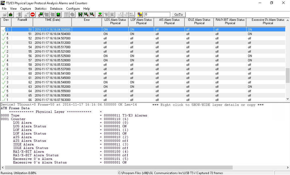
Detail View of T3 E3 Alarms
The summary view displays which alarm has occurred along with the particular timestamp and error counts. It also indicates the Frequency and Level for the counters.
Error Counters
Frequency: This shows the T1 E1 line frequency in Hertz (Hz)
Level: This shows the T1 E1 line power in dBm
Detail View of T1 E1 Counters
Detail View of T3 E3 Counters
Sending SNMP Traps from Physical Layer Analyzer
Physical Layer Analyzer can send SNMP traps to one or more SNMP notification receivers.
Physical Layer Analyzers continuously captures alarms on T3 E3 and T1 E1 ports. Physical Layer Analyzer sends SNMP traps when alarm status changes to SNMP monitoring applications specified by an IP Address and a UDP port.
SNMP traps data are monitored at NOC using any SNMP Monitoring Application as shown below.
DS3 SNMPv2 Traps
DS1 SNMPv2 Traps
Unchannelized-T3 E3
Accompanying Basic & Optional Software
A list of all the basic applications and other optional applications (requiring additional licenses).
Supported Protocol Standards for Unchannelized T3 E3 Analyzer
HDLC
- Analyze HDLC frames over bidirectional T3 E3 with host of protocol analyzer features such as Real-time filter, Capture filter, Statistics, and so on
- Captured frames can later be used for traffic simulation using HDLC Transmit/Receive/Playback and Impairment applications
For more information, please visit HDLC Protocol Analysis over T3 E3
Frame Relay
- Analyze Frame Relay protocol over bidirectional T3 E3 with host of protocol analyzer features such as Real-time filter, Capture filter, Statistics, Call Trace, and so on
- Analyze Permanent Virtual Connection (PVC) and Switched Virtual Connection (SVC) frames
- Call Trace view displays called/ calling number, released calls, call status, & more
For more information, please visit Frame Relay Protocol Analysis over T3 E3
ATM
- Support of various UNI Signaling Protocols i.e. UNI 4.0, UNI 3.1 and UNI Q-2931
- Call trace capability based on UNI signaling parameters, VPI/VCI and others
- CRC verification for AAL5 carrying packet data
For more information, please visit ATM Protocol Analysis over T3 E3
PPP
- Supports a host of protocols PPP, IPCP, BCP, BPDU, PAP, CHAP, HTTP, SNMP, STUN, FTP, DNS, and DHCP
- Ability to test and perform numerous measurements across WAN- LAN or LAN-LAN connection
- Supports Packet Data Analysis module (requires additional license) to perform detail analysis of PPP packets over IP and segregates them into SIP/H323/Megaco/MGCP/T.38/IuCS/GSM A Fax calls
For more information, please visit PPP Protocol Analysis over T3 E3
DSU Subrate Configuration
Subrate allows DSU manufacturers to control bandwidth from service provider end and sell user specific bandwidth. USB T3 E3 Analyzer supports DSU DS3 Subrate configuration for Digital Link, Larscom, Verilink, and Adtran as shown in the figure.
For more details refer to T3 (DS3) Subrate and Scrambling webpage.
Bit Error Rate Test (BERT)
GL's T3 E3 Bit Error Rate Tester application measures the correctness of data received on T3 E3 channels for a repetitive fixed or pseudorandom pattern for the given transmission. BERT provides a figurative measurement of the number of erroneous bits received for the total number of bits transmitted.
GL’s USB T3 E3 BERT Windows Client Server task (BWT) implements the functionality of the Enhanced BERT GUI application for T3 E3 WCS Server. T3 E3 WCS commands is used to setup all ports to unstructured mode and all framing formats such as unframed, M13, E13, and C-bit. BERT can be run and tested on all framing formats.
For more details, refer to Bit Error Rate Testing (BERT) for T3 E3 Analyzer webpage.
Channelized-T3 E3
Features
- Provides support for channelized T3 E3 to T1 E1
- Supports up to 28 T1s and 16 E1s channels per T3 E3 port, in total it supports up to 56 T1s and 32 E1s
- Analysis of all 56 T1s (1.544 Mbps each), or 32 E1s (2.048 Mbps each)
- Analysis of Fractional T1s and E1s, N x T1s or N x E1s
- Analysis of any combination of DS0s (64 kbps each) within the T1s or E1s,
56 x 24 = 1,344 DS0s for T1 or 32 x 32 = 1024 DS0s - Supports structured and unstructured T1 E1 transmission and reception
- Supports all of the monitoring applications under "basic applications" and "special applications (licensed)" for T1 or E1 channels
- Supports Protocol Analysis of all structured protocols – HDLC, ISDN, CAS, and more
- Supports monitoring of T1 E1 alarms in channelized T3 E3 lines
- Comprehensive analysis of voice, data, fax, protocol, analog, and digital signals, including echo and voice quality testing
- Extracting T1s E1s from multiple T3 E3 ports is supported
- User selectable T1 and E1 channels to multiplex. The channel numbering is same as in De-multiplexing
- Unused channels will be treated as unequipped
- Broadcasts the selected T1 E1 channel data on all the 32 E1’s or 56 T1’s
Working Principle
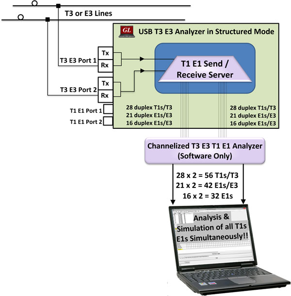
The T3 E3 hardware platform with associated T1 E1 Send/Receive Server and Channelized T3 E3 analyzer software can generate, capture, record, and monitor multiple T1 or E1 channels over Channelized T3 E3 links. It can perform analysis of various signal types including voice, digits, tones, fax, modem, and raw data.
The Channelized T3 E3 to T1 E1 solution, comprises of two modules, namely, the High-Speed T3 E3, and Low-Speed T1 E1 modules. These two modules are actually two separate processes running on the same computer. The High-Speed T3 E3 process is called as T1 E1 Send/Receive Server, as the name suggests it runs as a service and works with USB T3 E3 hardware. The Low-Speed T1 E1 module part is referred to as Channelized T3 E3 analyzer software.
The T1 E1 Receive Server application within USB T3 E3 analyzer acts as software-based Multiplexer- Demultiplexer application capable of channelization of a T3 signal into 56 independent T1 channels and an E3 signal into 32 E1 channels. The channelized streams containing T1 E1 frames are forwarded to T3 E3 Channelized T1 E1 analyzer software over UDP using GL Message Protocol for analysing frames per channel.
ISDN Analysis over T3 E3 Signals (56 T1s)
Accompanying Basic Software/Features
Almost all the basic and optional monitoring applications supported by T1 E1 analyzers are also supported by Channelized T3 E3 T1 E1 analyzer. For example, capturing an entire T1 E1 signal, or performing ISDN, or SS7 analysis, can be performed using the software accompanying the Channelized T3 E3 T1 E1 analyzer.
- A list of all the basic applications and other optional applications (requiring additional licenses)
Resources
| Item No. | Item Description |
TE3001 |
Portable (USB) Dual T3 E3/T1 E1 Hardware Unit – requires TT3001 or EE3001 |
| MT001 | mTOP™ 1U Rack Mount Enclosure w/SBC (intel core i3) |
| MT001E | mTOP™ Rack Mount Enclosure w/SBC (intel core i7) |
| MT002 | mTOP™ 1U Rack Mount Enclosure w/o SBC |
| MT005 | mTOP™ Probe (Portable Stand-alone) (intel core i3) |
| MT005E | mTOP™ Probe (Portable Stand-alone) (intel core i7) |
| UnChannelized T3 E3 Testing | |
|---|---|
EE3001 |
E3 E1 Analyzer Basic Software |
TT3001 |
T3 T1 E1 Analyzer Basic Software |
TT3020/ EE3020 |
T3 E3 Record Playback Software (GUI) |
TT3090 / EE3090 |
T3 E3 HDLC Tx/Rx Test + Analyzer (GUI) |
TT3135 / EE3135 |
T3 E3 PPP Analyzer (GUI) |
TT3136 / EE3136 |
|
TT3130 / EE3130 |
T3 E3 Frame Relay Analyzer (GUI) |
TT3160 |
T3 ATM Analyzer (GUI) |
TT3600 / EE3600 |
|
TT3610 / EE3610 |
T3 E3 Client Server Tx/Rx File |
TT3634 / EE3634 |
T3 E3 Client Server High Throughput HDLC Tx/Rx Test |
| Channelized T3 E3 T1 E1 Testing | |
EE3001 |
E3 E1 Analyzer Basic Software |
TT3001 |
T3 T1 E1 Analyzer Basic Software |
TT3200 |
Optional Channelized T3 license for T1 |
TT3210 |
Optional Channelized T3 License for E1 |
EE3200 |
Optional Channelized E3 license for E1 |
TTTxxx |
Channelized Options for T1 |
| Related Hardware | |
SA004A |
T3 E3 Accessory Kit |
UT301 / UT302 |
T3 Analysis PCI Card w/ Basic Software and Client/Server and Command Line Utility |
SA000d |
High Stability Internal Clock Option |
PTE001 |
|
FTE001 |
QuadXpress T1 E1 Main Board (Quad Port– requires additional licenses) |
| Webinars |
|