ExpertTCP™ - TCP Throughput Testing (RFC 6349)
RFC 6349 based TCP Throughput test methodology referred to as ExpertTCP™ capable of generating and analyzing multiple TCP streams up to 1 Gbps rate.
Request a Demo / Quote Brochure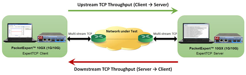
Overview
ExpertTCP™ is an optional application with GL's PacketExpert™, (PXE100, PXN100) Ethernet/IP Networks Test platform. ExpertTCP™ testing is performed using the RFC 6349 standard. To conduct this test, users need two PacketExpert™ devices - one as the client and the other as the server. The ExpertTCP™ test covers both upload (Client to Server) and download (Server to Client), measuring TCP throughput and efficiency.
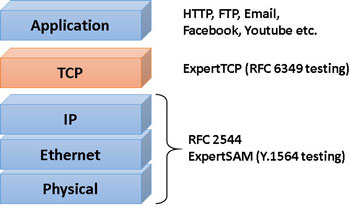
IP Network operators and Service providers need to verify that their networks are performing well and meet the Service Level Agreements (SLA) with the customers. To verify Ethernet/IP based networks, current widely used standards are RFC 2544 or Y.1564. However, both these standards are meant for testing at Layer 2 or Layer 3 (Ethernet or IP layers).
Though these tests are necessary, they are not sufficient, because they do not cover testing at TCP layer. Most web based applications like Http, FTP, E-mail etc. run over TCP. Even many modern web applications like Facebook, Youtube, and the like use TCP.
Even if service provider networks are tested using RFC 2544 or Y.1564, customers may still face problems with TCP throughput. The TCP throughput may not match the throughput at the Ethernet/IP layer. This is because TCP throughput depends on factors like the TCP Window Size, buffer size of intermediate network nodes etc. Also, impairments like latency and packet drops causes TCP retransmissions, severely affecting the TCP throughput. So, there is a gap in the current testing methods and to cover the gap, RFC 6349 frame work has been devised.
The PacketExpert™ test platforms have been enhanced to support RFC 6349 based TCP Throughput test methodology for both 10Gbps and 1Gbps networks. Although RFC 6349 is supported on 10 Gbps ports, the maximum TCP generation rate is limited to 1 Gbps due to constraints of the hardware-based FPGA TCP implementation.
GL's ExpertTCP™ test methodology is based on the RFC 6349 to measure TCP throughput, RTT and optimal window size. It has the capability to Generate and Analyze up to 8 TCP streams of traffic on 1G platform (PXE100), and up to 16 TCP streams of traffic on 10G platform (PXN100) of varying packet lengths. It also performs bi-directional TCP throughput measurements in combination with another unit at the remote location (other end of the network), that acts as the TCP server, as depicted in the figure above. Many real-world networks are not symmetrical. There may be significant differences between upstream and downstream directions. ExpertTCP™ supports both Upstream (Client → Server) and Downstream (Server → Client) direction testing.
ExpertTCP™ supports unidirectional or simultaneous bi-directional testing, with results reported for each direction. The remote server is fully controlled by the local client, allowing users to configure both client and server from a single location. This eliminates the complexity of managing test setups across multiple sites. For bi-directional or unidirectional testing, two PacketExpert™ devices are required to conduct the test. One device acts as the TCP client and the other as TCP server.
GL's PacketExpert™ platforms are also capable of Bit Error Rate Testing (BERT), Smart Loopback, RFC 2544 Testing, Wirespeed Record and Playback, Multi Stream UDP/TCP Traffic Generator and Analyzer , PacketBroker™, IP WAN Emulation, and Y.1564 (ExpertSAM™) Testing.
Important Features
- Supports Path MTU, Baseline RTT and TCP Throughput tests
- Support for frame lengths from 64 bytes to Jumbo frames (up to 16000 bytes)
- Hardware FPGA based TCP implementation supports full duplex bidirectional wirespeed TCP (up to 1 Gbps in both directions simultaneously)
- Supports multiple TCP connections (up to 16 TCP connections for PXN100 and up to 8 TCP connections for PXE100)
- Upstream (Local to Remote), Downstream (Remote to Local) and Bi-directional tests supported
- Test asymmetrical path with separate set of configurations for Upstream and Downstream
- Complete remote control - user needs to interact only with Local side - all results/statistics (both local and remote side) provided on local side
- Detailed run time statistics with Graphs for easy visualizations
- RFC 6349 specified metrics - TCP Efficiency, Buffer Delay Percentage, TCP Transfer Time ratio
- Command Line Interface for automated testing and remote accessibility
Functional Procedure
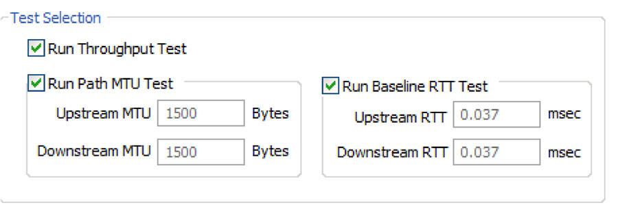
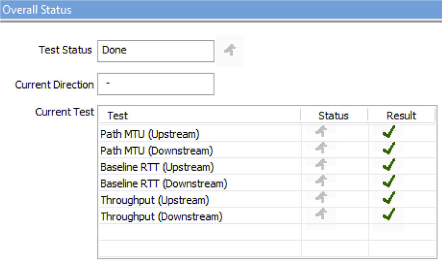
ExpertTCP™ (RFC 6349) specifies the TCP Throughput test to be conducted in 3 steps:
- Path MTU Discovery
- Determine Baseline RTT
- Conduct TCP Throughput test
ExpertTCP™ supports all 3 tests in a seamless one touch way. User can configure the parameters and simply start the test. ExpertTCP™ will run through all the three tests and report the results.
Path MTU Discovery – As per RFC 6349, the first step is to discover the Path Maximum Transmission Unit (MTU). This is because the TCP Throughput test has to be conducted at the Path MTU, else the TCP segments can fragment, adversely affecting the test results.
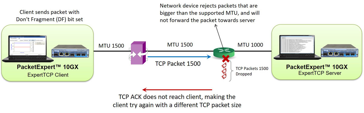
ExpertTCP™ discovers the Path MTU for both directions (Upstream/Downstream) separately. It follows a method similar to the one specified in the RFC 4821 (Packetization Layer Path MTU Discovery) standard, but uses TCP instead of ICMP.
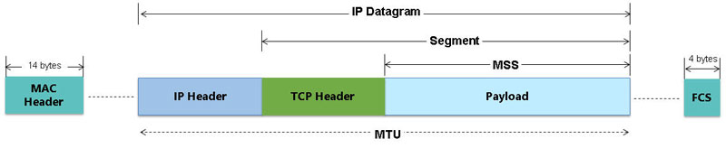
Path MTU determines the Maximum Segment Size (MSS) that TCP can use during the test.
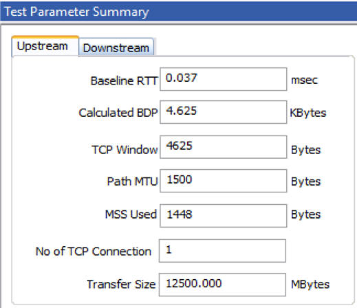
Determine Baseline RTT - This step establishes the inherent, non-congested Round-Trip Time (RTT) of the end-to-end network path. TCP RTT is the time taken for a TCP data packet to reach the other end, and for the corresponding ACK packet to reach the sender.

RTT is an important metric in TCP, as the path RTT determines how much data can be sent out on the wire before an ACK can be received. This measurement is used to provide estimates of the TCP Receiver Window (TCP RWND) that should be used during subsequent Throughput test.
ExpertTCP™ performs Baseline RTT test separately for each direction and automatically calculates the optimum TCP RWND size based on the results. The Bandwidth Delay Product (BDP) and the RWND are displayed for user reference.
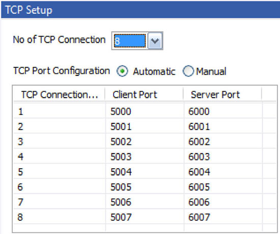
Conduct TCP Throughput test – In this step, single/multiple TCP connection Throughput tests are conducted and the TCP Throughput is determined. The TCP RWND determined during the Baseline RTT test is used. For multiple TCP connections, the RWND is distributed among the connections.
Up to 8 TCP connections are supported on 1G platform (PXE100), whereas up to 16 TCP connections are supported on 10G platform (PXN100).
Statistics and Results
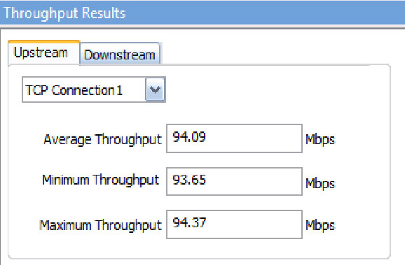
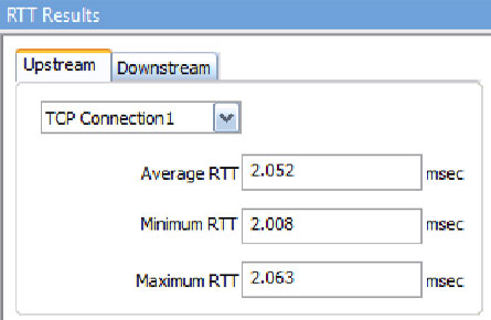
Various statistics at runtime such as minimum, maximum and average Throughput, and RTT measurements per connection provide detail insight into the performance.
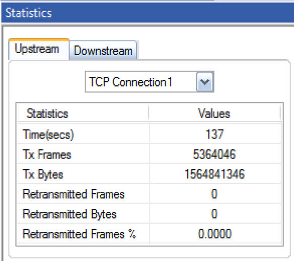
The statistics information on number of frames and bytes Transmitted, and Retransmitted per connection, gives a snapshot of the performance.
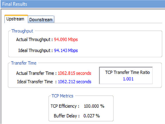
Final Results include the comparison of the actual Throughput/Transfer time with the ideal values. The three RFC 6349 TCP metrics defined in the specification - Transfer Time Ratio, TCP Efficiency and Buffer Delay are reported here.
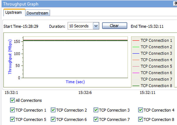
Various graphs are available for visualizations. Throughput graph plots the Throughput over time. All connections are plotted in a single graph for a comprehensive view of the overall performance.
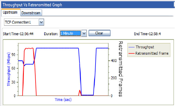
Throughput vs. Retransmissions graph provides insight into how Retransmissions are affecting the Throughput.
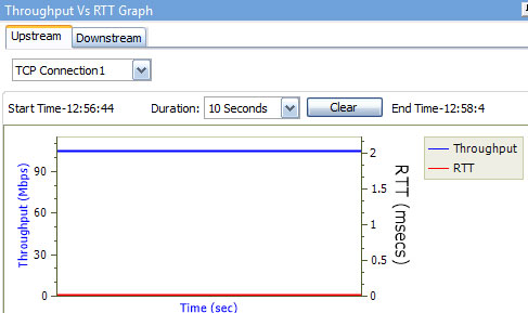
Throughput vs. RTT graph visualizes how the RTT variation affects the TCP Throughput.
Resources
Note: PCs which include GL hardware/software require Intel or AMD processors for compliance.
Please Note: The XX in the Item No. refers to the hardware platform, listed at the bottom of the Buyer's Guide, which the software will be running on. Therefore, XX can either be ETA or EEA (Octal/Quad Boards), PTA or PEA (tProbe Units), XUT or XUE (Dual PCIe Express) depending upon the hardware.
| Item | Description |
|---|---|
| PXN100 | PacketExpert™ 10GX |
| PXE100 | PacketExpert™ 1G |
| PXN108 | Multi-Stream UDP/TCP Traffic Generator and Analyzer – for PXN100 |
| PXE108 | Multi-Stream UDP/TCP Traffic Generator and Analyzer - for PXE100 |
| CXN100 | CLI Server for PXN100 |
| CXE100 | CLI Server for PXE100 |
| PacketExpert™ 10GX - Brochures |
|---|
| PacketExpert™ 10GX |
| PacketExpert™ 10GX - ExpertTCP |
| PacketExpert™ 10GX mTOP™ |
| PacketExpert™ 10GX CLI |
| PacketExpert™ 1G - Brochures |
| PacketExpert™ 1G |
| PacketExpert™ 1G - ExpertTCP |
| PacketExpert™ 1G - mTOP™ |
| PacketExpert™ 10GX - Presentations |
| PacketExpert™ 10GX |
| PacketExpert™ 10GX - ExpertTCP |
| PacketExpert™ 1G - Presentations |
| PacketExpert™ 1G |
| PacketExpert™ 1G - ExpertTCP |
Webinar
Comprehensive Ethernet Testing Solutions
ExpertTCP™ - TCP Throughput Testing Methodology