Jitter Generation on T1 E1 Lines
Welcome to another September, 2013 issue of GL Communications' Newsletter providing information and insight into our Jitter Generation Software for T1 E1 Lines.

Overview
When a signal traverses a network, the jitter generated by a DUT becomes the input jitter to the next part of the network. If this jitter is amplified, it can exceed the jitter tolerance of the subsequent DUT. In this way, excessive jitter may accumulate and cause errors as the signal progresses through the network equipment.

It is quite common for T1 E1 signals, within a central office environment or an enterprise telecom room, to NOT meet pulse mask requirements due to interference, too long or short cable lengths, improper impedances, or simply poor transmitter design. In such cases, jitter measurement & pulse mask compliance is very useful in diagnosing problems.
The jitter and pulse mask compliance test capability is available in GL's Dual T1 E1 Express (PCIe) Boards and tProbe™ T1 E1 Analyzer platforms.
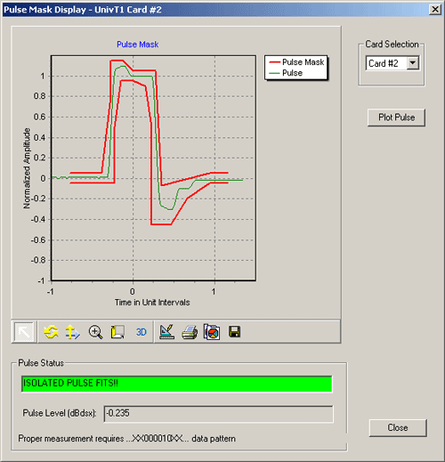
GL's Pulse Shape Measurement software can determine if the pulse shape fits within a "pulse mask" as specified by standards ITU G.703 and ANSI T1.102-1993. The software is available in both visual and tabular formats. Tabular formats are convenient for automation and scripted test environments.

GL's Jitter Measurement software allows one to accurately measure jitter associated with a incoming T1 E1 signals. It also allows evaluation of the jitter on either a tick-by-tick or a cumulative basis. In addition to these, the application recognizes the very slow variations in a clock signal (below 1 Hz), and the Frequency Offset or Deviations in clock rates. This application in conjunction with GL's Jitter Generation application can be used to test jitter transfer function to confirm that there is no amplification of jitter by network elements (NEs) in the transmission system.

GL's Jitter Generation software has been developed to generate a jittered output T1 E1 signal with user-selected frequency and amplitude. It is suitable for testing jitter tolerance and compliance with standards such as G.823.
The specification section below provides Jitter tolerance mask defined as per the standard specification. Jitter tolerance mask defines a boundary to tolerate intrinsic jitter. Jitter tolerance mask can be defined in the jitter generation software as per the transmission standard to create a benchmark for the generated jitter.
Once jitter is generated beyond the tolerance level, the DUT starts to introduce frame errors due to the applied data transition jitter. This can be verified using the Bit Error Rate (BER) Tester. The line sync loss and bipolar violations are also indicated for each port in the T1 E1 Line status window.
Specification
Important Features
- Generates intrinsic jitter without any error as per G.823 standards
- Generates user-defined jitter value against an input jitter tolerance mask to test DUTs capability to tolerate large amounts of generated jitter.
- In conjunction with Jitter Measurement provides peak-to-peak jitter value for a given frequency at the system output
- Evaluate the jitter in real-time on either a tick-by-tick or a cumulative basis
For comprehensive information on the software, you can visit Jitter Generation Software on T1 or E1 Lines web page.


 Back to Newsletter Index Page