T1 E1 Signaling Bits Recorder/Analyzer
Signaling Bits Recorder application is included with T1 E1 Basic Software
Description
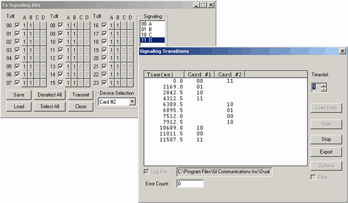
This optional software provides time stamped indications of all signaling bit changes. The application works with one or multiple Dual T1 E1 Express (PCIe) Boards or with the Portable T1 E1 Analyzers. Signaling bit changes are recorded for all timeslots simultaneously. A file may be specified for saving the captured signaling transitions. A previously recorded file may be viewed by "loading" the respective file.
Features
- Continuous full-duplex recording of signaling bits for any or all channels for any length of time
- Permits detailed analysis of recorded signaling bits for any channel
- Applications include call duration, wink analysis, abnormal terminations, call setup, etc.
- Live T1 E1 signal is not disturbed
- Recording can continue for extended periods of time
- Recording can be terminated at any time manually
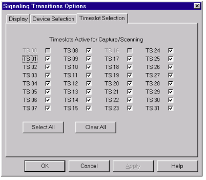
- User has the choice of recording the data from selected channels or from all the channels
Additional Features
This same application can also provide timestamped indications of all extra bit changes for E1 systems. Note that extra bit transitions are not displayed on a timeslot-by-timeslot basis, as are signaling bits.
Error Count: Informs the user whether any received data was skipped.
Load Data: Permits viewing of a previously recorded file (".sig" or ".ext" extension).
Receive: Activates signaling or extra bit transition recording.
Stop: Stops recording of signaling or extra bit transitions.
Log File: Records all transitions to a binary file. The extension ".sig" is appended for signaling transitions, ".ext" for extra bit transitions. These transitions can be exported into an ASCII file. See the Export section.
Export: Dumps the contents of a binary log file to an ASCII file. These can be signaling or extra bit files.
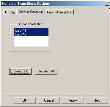
Options: Enables selection/deselection of devices and timeslots. If all devices and timeslots are selected, processing time will be significantly greater.
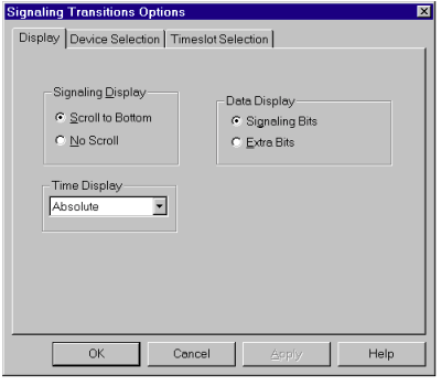
The Display page allows the user to select the type of timestamp that is displayed, absolute or differential. By default, absolute timestamping is enabled & Differential timestamping is disabled. In the case of differential timestamping, the time elapsed since the last transition is displayed. In absolute timestamping, the application displays the time elapsed since it started scanning for transitions.
Different methods of viewing the real-time display are provided. The "Scroll to Bottom" feature forces the display of the latest real-time transitions. The "No Scroll" feature allows the user to view transitions of any time period in the display.
Filter:
Filtering adds new versatility to the Signaling Transitions application. In many cases, noise interference can cause volatility and introduce extra transitions, which may cause miscomprehension. By enabling this option, a momentary or sudden change in the transition can be removed.
For example, if signaling bits are giving a constant reading, and noise introduces a sudden change in one of those signaling bits.
If the change is only momentary, filtering will remove that intermediate transition.
0010->0000->0010 Without filtering
10 With filtering
For example, consider an On-hook condition defined as 0000 and Off-hook defined as 1111. It's possible that an on hook to offhook transition will produce momentary transition states that appear as given below in consecutive multiframes.
2.0 4.0 6.0 (ms)
0000->0011->1111 Without filtering
2.0 4.0 (ms)
0000->1111 With filtering
Example Use:
Method 1 - Cross connect port1 and port2 of T1 E1 card then transmit a tone into a timeslot of your choice; observe the signaling bit changes being recorded as you modify the signaling bits from "offhook" to "onhook".
Method 2 - Cross connect port1 and port2 of T1 E1 card and invoke the "transmit signaling bits" application twice, one
for the first card and another for the second card. Modify the signaling bits by selecting an "ABCD" pattern from the right. Notice
the change on the "signaling bit transition" screen.
Screenshots
MFC-R2 Analysis and Emulation
GL's MFCR2 Analysis & Emulation solutions use any of the following hardware:
- T1 E1 Analyzer (Potable USB or Ultra HD PCI cards or Universal Cards) Or
- DCOSS (Digital Central Office Switch Simulator)
Both the products supports remote capture & analysis using client-server technology,while DCOSS is ideal for simulating and testing advanced telecom networks and products, including switches, gateways, and transmission systems.
Resources
Please Note: The XX in the Item No. refers to the hardware platform, listed at the bottom of the Buyer's Guide, which the software will be running on. Therefore, XX can either be ETA or EEA (Octal/Quad Boards), PTA or PEA (tProbe Units), XUT or XUE (Dual PCIe Express) depending upon the hardware.
| Item No. | Item Description |
| XX050 | Signaling Bits Recorder Software |
| Related Software | |
|---|---|
| XX020 | Record and Playback of Files |
| XX051 | Synchronous Trunk Record Playback |
| XX022 | DTMF/MF/MFC-R2 Detector & Generator Software |
| XX031 | Enhanced T1 E1 Call Capture/Analysis Software |
| XX100 | T1 E1 Real-Time ISDN Analyzer |
| XX120 | T1 E1 Real-Time SS7 Protocol Analyzer |
| Related Hardware | |
| PTE001 | tProbe™ Dual T1 E1 Laptop Analyzer with Basic Analyzer Software |
| FTE001 ETE001 |
QuadXpress T1 E1 Main Board (Quad Port– requires additional licenses) OctalXpress T1 E1 Main Board plus Daughter Board (Octal Port– requires additional licenses) |
| XTE001 | Dual T1 E1 Express (PCIe) Boards (requires additional licenses) |
| Brochures |
| T1 E1 Signaling Transition - Brochure |


 Back to Call & Signaling Analysis Index Page