Pulse Mask Compliance Testing
Pulse Mask Compliance application is included with T1 E1 Basic Software
Overview
It is quite common for T1 E1 signals, within a central office environment or an enterprise telecom room, to NOT meet pulse mask requirements due to interference, too long or short cable lengths, improper impedances, or simply poor transmitter design. In such cases, pulse mask compliance is very useful in diagnosing problems.
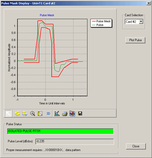
The Pulse Mask Compliance software has been developed to determine if the pulse shape fits within a "pulse mask" as specified by standards ITU G.703 and ANSI T1.102-1993. The software is available in both visual and tabular formats. Tabular formats are convenient for automation and scripted test environments.
The pulse shape measurement capability is available in GL's Dual T1/E1 Express (PCIe) boards, tProbe™ T1/E1 Analyzer units.
Now, Jitter Generation and Measurement, Pulse Mask Compliance (XX012) application is available as a part of basic applications in T1 E1 analyzer.
Background
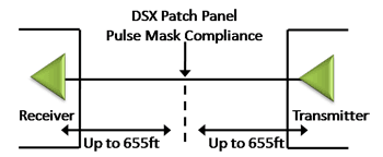
In T1 E1 transmission systems, signals are dropped, inserted, and accessed at the electrical level at a point called DSX patch panel or at some similar point. To reliably receive, monitor, or access these signals, they must first conform to a standard that establishes parameters such as pulse width, rise time, amplitude, allowable undershoot and overshoot. If the pulse meets the pulse mask, then a properly designed receiver should be able to decode the bits transmitted. See diagram below.
Main Features
- Plots the pulse measured within a predefined template
- Compares the incoming T1/E1 pulses against the pulse mask display
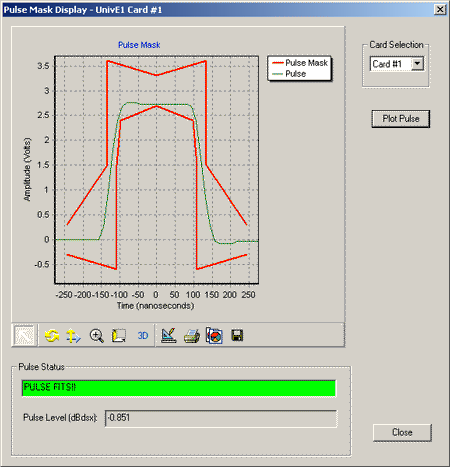
- For T1 pulses, the x-axis measures time in unit intervals (UI), while for E1 pulse, the x-axis measures time in nanoseconds (ns)
- The y-axis measures the normalized amplitude in volts
- The Pulse Mask image can be saved to a file, zoomed-in/zoomed-out, printed, and more
Operation
T1 Pulse Mask
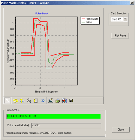
The transmit data path is selected and measured at the end of the transmission line for each T1 line. The specification for T1 requires that the T1 signal must fit within the pulse mask at the end of the line when transmitting an isolated pulse. Regardless of the way the T1 device is configured. The amplitude of the isolated signal at time zero should be within 20% of 3.0 volts. If the amplitude requirement is met, then the signal is scaled linearly to determine if it fits the pulse mask.
Plots a pulse against the mask, with the pulse mask x-axis measures time in unit intervals (UI), where 1UI is the nominal time to transmit one T1 bit - 648ns. The y-axis measures pulse voltage in normalized amplitude: the pulse voltage is scaled to fit the mask.
E1 Pulse Mask
The specification for E1 requires that all the pulses meet the template and not just an isolated pulse. Another difference is the fact that that pulses are measured at transmitter output, rather than after some length of cable, while T1 pulses must meet the template for the entire line length. There are two types of cables used in E1 mode: 75 Ohm coax cable and a 120 Ohm twisted pair. Both cables have different nominal amplitudes associated with them. For the 75 Ohm coax cable, the amplitude must be 2.37V ~ 10% at T0. For the 120 Ohm twisted pair, the amplitude must be 3.0V ~ 10%.
WCS Pulse Mask
The Pulse Mask compliance testing can be performed through commands with the Windows Client-Server application. The pulse mask can be remotely controlled using simple commands by client applications. Some of the commands supported are CheckPulseMask, validate pulse, stop pulse mask validation, and others.
For complete information, visit WCS Pulse Mask webpage.
Jitter Measurement
GL's jitter measurement software allows one to accurately measure jitter associated with T1 or E1 signals. The module allows evaluation of jitter on either a tick-by-tick or a cumulative basis.
For more information, visit Jitter Measurement webpage.
Jitter Generation
GL's Jitter generation software has been developed to generate jittered output T1/E1 signal with the user-selected frequency and amplitude in compliance with standards such as G.823. In conjunction with GL's Jitter Measurement application, Jitter Generation may be used to test jitter transfer. Jitter transfer measurement is required to confirm that there is no amplification of jitter by network elements (NEs) in the transmission system.
For more information, visit Jitter Measurement webpage.
Buyer's Guide
Please Note1: The XX in the Item No. refers to the hardware platform, listed at the bottom of the Buyer's Guide, which the software will be running on. Therefore, XX can either be ETA or EEA (Octal/Quad Boards), PTA or PEA (tProbe Units), XUT or XUE (Dual PCIe Express) depending upon the hardware.| Item No. | Item Description |
| Pulse Mask Compliance, Jitter Generation, and Jitter Measurement (Available as a part of basic applications in T1 E1 analyzer) Easy, accurate, visual pulse shape and jitter measurement for T1 E1 signals |
|
| Related Hardware | |
|---|---|
| XTE001 | Dual T1 E1 Express (PCIe) Boards (requires additional licenses) |
| PTE001 | tProbe™ T1E1 Analyzer |
| Brochures |
| Product Brochure |
| GL Product Lists |
| Presentations |
| Pulse Mask Compliance Testing Presentation |
 Back to List of T1E1 Basic and Optional Applications Index Page


