GL Enhances MEGACO (H.248) Emulator with Binary Encoding
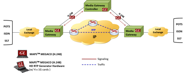
Welcome to another March 2016 issue of GL's Newsletter providing information and insight into our latest MAPS™ MEGACO (H.248) Emulator that’s now enhanced to support H.248 protocol simulation in 2G, 3G and VoIP networks using Binary Encoding format as per 3GPP specifications. A typical MEGACO (H.248) based VoIP network is shown below.
Overview
The Media Gateway Control Protocol (MEGACO/H.248) is a signaling and call control protocol used between the Media Gateway Controller (MGC) and Media Gateway (MG) for supporting multimedia stream transmission. In a 2G/3G core network, the MSC server (or GMSC Server) controls MG over a 3GPP interface, termed as Mc interface. The MSC (or GMSC) server supports the call control and mobility management functions, and the Media Gateway provides the bearer control and transmission resource functions.
The MEGACO protocol is implemented in binary encoding over 2G/3G core network. However, it can be still used in traditional text based encoding in IP networks as well. It is typically used for providing Voice over Internet Protocol (VoIP) services like voice and fax between different networks - such as IP Networks and the PSTN, IP Networks and Wireless Networks (2G/3G) or entirely within IP Networks.
Functional Procedure
GL's MAPS™ (MEGACO /H.248) can simulate both MSC and MG network elements across Mc interface in 2G/3G and VoIP networks.
GL’s MAPS™ MEGACO (H.248) protocol emulator now supports binary encoding along with existing textual encoding. The binary encoding is based on Basic Encoding Rules (BER) description of the protocol and text encoding is based on Augmented Backus-Naur Form (ABNF) description.
The main picture above shows MEGACO (H.248) in 2G, 3G CS core. The CS core network includes the MSC server, GMSC server and Media Gateways. The GMSC server and MSC servers are connected to the media gateway via the Mc interface. The H.248 protocol together with 3GPP specific extensions or packages is used over the Mc interface.
The MSC servers and GMSC servers are connected via Nc interface. Any suitable call control protocol may be used over the Nc interface (e.g. BICC Protocol). The GMSC server and MSC server supports the call control and mobility management functions, and the media gateway provides the bearer control and transmission resource functions.
Supported Protocol Standards
| Supported Protocols | Standard / Specification Use |
| MEGACO/H.248 | IETF RFC 3525 / ITU-T Recommendation H.248, ETSI TS 102 374-2 (2004-11) ITU-T Rec. H.248.45 ITU-T Rec. H.248.59 (08/2007) ITU-T Rec. Q.1950 (12/2002) ITU-T Rec. H.248.14 (03/2002) 3GPP TS 29.232 v5.6.0 3GPP TS 29.232 v4.1.0 T-REC-H.248.1-201303-I!!PDF-E.pdf Q.1950 Annex A |
Important Features
- Complete end to end test environment for 2G, 3G and VoIP networks
- Generates and processes H.248 valid and invalid messages
- Support for both text based and binary based syntax encoding
- Simulates Media Gateway Controller (MGC) and Media Gateway (MG) in IP Networks
- Simulates MSC (or GMSC) and Media Gateway (MG) in 2G/3G Networks
- Tests Media Gateway Controller functionalities
- End-to-end Gateway Testing
- Multi-protocol call trace for 2G, 3G, PSTN calls
- Supports commands such as Add, Subtract, Notify, Modify, Move, Service Change, Audit Value, and Audit Capabilities
- Supports message templates for each MEGACO message and customization of the field values
- Facilitates defining variables for the various protocol fields of the selected MEGACO message type
- Supports almost all industry standard codec types - G.711 (mu-Law and A-Law), G.722, G.729, G.726, GSM, AMR, AMR -WB, EVRC, EVS, OPUS, SMV, iLBC, SPEEX, and more. *AMR, EVRC, EVS, and OPUS variants require additional licenses.
- Supports transmission and detection of various RTP traffic such as digits, voice file, single tone, and dual tones in IP networks
- Supports 64-bit version to enhance signaling performance, and to handle increased call rate of up to 3000 calls with high volume traffic
- Automation, Remote access, and Schedulers to run tests 24/7
- Supports Client-Server functionality (requires additional license) and supported clients include TCL, Python, VBScript, Java and .Net
Typical Call Procedure
Shown below is the typical call procedure in CS Network between MSC server and MG:
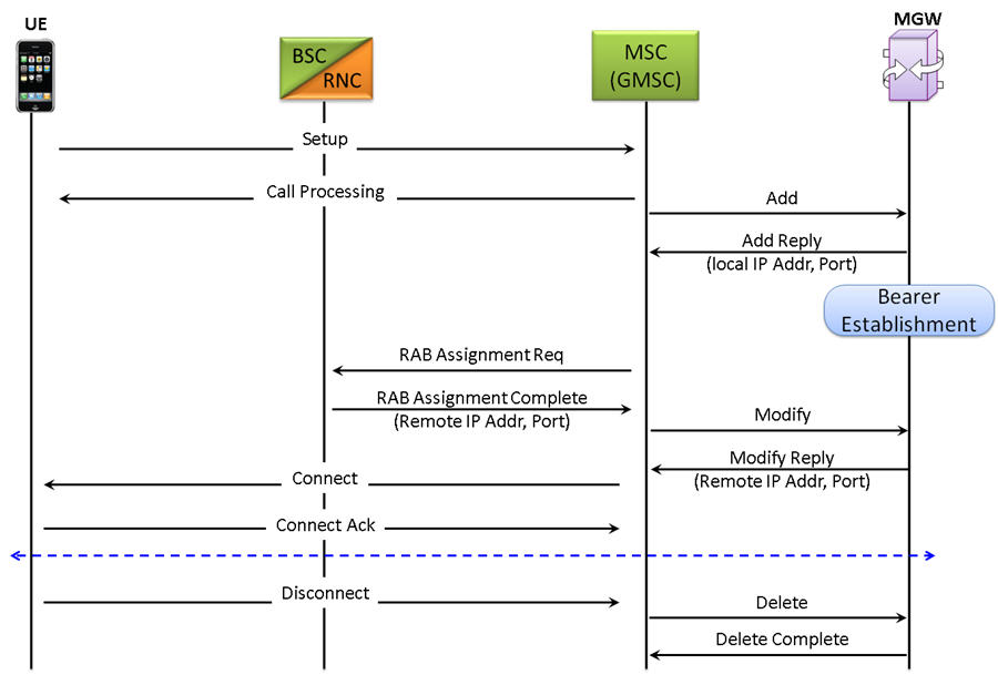
MSC server requests the MGW to prepare for access bearer establishment and to provide a bearer address and a binding reference. After the MGW has replied with the bearer address and binding reference, the MSC server requests access bearer assignment using the provided bearer details.
MSC sends request for the creation of the incoming and outgoing terminations with ADD procedure. MGW replies with the IP address and the port for the local descriptors (for Termination T1). The MSC server requests access bearer assignment using the IP address and UDP Port. The IP addresses and UDP Ports of the MGW and the RNC are exchanged via the RANAP procedures. MSC sends the RNC (Remote Descriptors) IP address and UDP Port to the MGW using the Modify procedure.
Now,the MSC server seizes this termination in MGW. The bearer termination T1 is used for the bearer towards the RNC/BSC and similarly the bearer termination T2 is added to context and is used for the bearer towards the GMSC server.
The MSC shall also request the possible activation of the interworking function in both terminations and the possible activation of the voice processing functions for the bearer terminations.
Call Generation Procedure
The following MAPS™ Call Generation application GUI depicting the typical MEGACO (H.248) call scenario with binary and textual message decodes shown below:
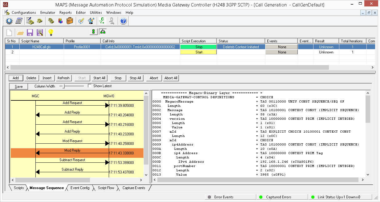
MAPS™ MEGACO (H.248) Call Generation
with Binary message decodes
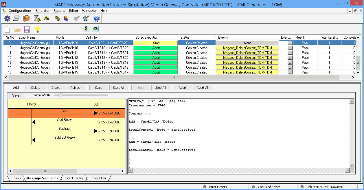
MAPS™ MEGACO (H.248) Call Generation
with Textual message decodes
 Back to Newsletter Index Page