DDS Protocol Analyzer
Overview
Conventional Digital Signal Services (DDS) data channel may utilize multiple, all, or a fractional timeslot of the T1 line, with the transmission rates of 2.4 kbps, 4.8 kbps, 9.6 kbps, 19.2 kbps, and 56 kbps. As depicted in the main diagram, the DDS circuit starts with customer premises equipment that can include a computer or a Data Terminal Equipment (DTE), a Data Service Unit (DSU)/Channel Service Unit (CSU).
The Unformatted customer data are transmitted from the DTE, and then passed through a DSU/CSU before being transmitted over the local loop. Depending on the length of the loop, repeaters may be needed along the loop to regenerate the signal.
The local loop signal is formatted into a DS0 signal by the Office Channel Unit-Data-Port card (OCU-DP) and multiplexes the customer signal into one of the 24 timeslots of a T1 signal. DDS networks accept data from the customer at various standard rates. Full-duplex, synchronous data transmission has been available at 56kbps and standard sub-rates of 2.4 kbps, 4.8 kbps, 9.6 kbps etc. To multiplex a sub rate signal into a 64 kbps time slot, DDS uses a technique known as Byte Stuffing, by which, customer information is repeated the required number of times to create a 64 kbps DS0 signal.
Normal testing methods used to verify DDS circuits are -
- BERT Testing at DS0 level with standard set of pseudorandom and fixed patterns
- Subrate testing at 2.4, 4.8, 9.6,19.2, and up to 64 kbps
- Loopback or end-to-end tests to isolate faulty DDS circuits
- Non-Intrusive monitoring and analysis of frames at certain points within the network infrastructure or at customer premises
Non-Intrusive Capture and Analysis
GL supports non-intrusive monitoring and analysis of DDS frames using T1 Analyzer hardware. The captured data can be decoded and analyzed by GL’s DDS Protocol Analyzer (Item No: XX102). Currently the analyzer supports 9.6 kbps data rates only.
GL Communications supports real-time and offline DDS Protocol Analyzer (Pre-requisites: GL's field proven T1 internal PCI based analyzer cards or USB Laptop T1 based analyzer external units, required licenses and Windows® 7 or above Operating System). This helps in real-time and proactive monitoring and analysis.
Non-intrusive TAPs are used to passively duplicate the signal between two end points on a network link without disturbing the actual network activity. Any of GL’s T1 Analyzer hardware can be used with RJ48 Y Bridge (splits one RJ48 into two complete) to non-intrusively tap and capture the DDS frames on a T1 line.
The DDS data is formatted into frames separated by one or more bytes. The data channel may utilize multiple, all or a fractional timeslot of the T1 line. Also, there may be multiple data channels within the T1 line. The captured data analyzed using GL's DDS Protocol Analyzer application.
Main Features
Display Features |
|
Capturing Streams |
|
Export Options |
|
Additional Features |
|
Supported Platforms
GL Communications supports DDS Analyzer in the following T1 hardware platforms:
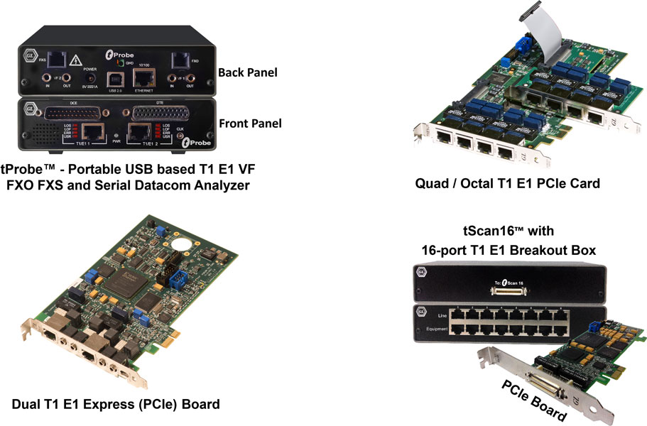
T1 Hardware Platforms for DDS Analysis
Typical Capture and Decode of DDS Digital Data at 9.6 kbps
A typical capture and decode of DDS from of 9.6 kbps is shown in the figure below. In this format, DDS OCUs regenerate customer data bytes 5 times for 9.6 kbps. This regeneration may be 10 times for 4.8 kbps, and 20 times for 2.4 kbps, depending on the customer requirements. The remaining bits are stuffed to get to create a 64 kbps DS0 signal.
From the incoming data, DDS analyzer considers only the first data byte value and ignores the next set of data bytes with same value. The analyzer then strips out the LSB and MSB bits from each byte value, and the remaining bits are grouped to detect the proper data bytes by flagging the start and stop bits.
Summary, Detail and Hex dump Views
The DDS analyzer application is invoked from the main menu of GL's T1 Analyzer for real-time analyzer. The analyzer displays Summary, Detail and Hex dump View in different panes. The Summary View displays Frame Number, Time, Length, Error, Subchannel, and Timeslot. User can select a frame in Summary View to analyze and decode each frame in the Detail View. The selected frame is analyzed and decoded according to DDS frame specifications. The Hex dump View displays the frame information in HEX and ASCII. The contents of Detail and Hex Dump view the contents of this view can also be copied to clipboard.
Real-time/Offline Analysis
Users can capture and analyze DDS frames using either real-time or offline analyzers, and record all into a trace file. The recorded trace file can be used for offline analysis or exported to a comma-delimited file, or ASCII file. Real-time capturing requires user to specify timeslots and data transmission rate. Sub channel and N x 56 hyper channel enables user to analyze data captured by fractional DS0 and DS1 link respectively.
Save/Load All Configuration Settings
Protocol Configuration window provides a consolidated interface for all the important settings required in the analyzer. This includes various options such as protocol selection, startup options, stream/interface selection, and so on. All the configuration settings done in any of these options can be saved to a file, loaded from a configuration file, or user may just revert to the default values using the default option.
Resources
Please Note: The XX in the Item No. refers to the hardware platform, listed at the bottom of the Buyer's Guide, which the software will be running on. Therefore, XX can either be ETA or EEA (Octal/Quad Boards), PTA or PEA (tProbe™ Units), UTA or UEA (USB Units), HUT or HUE (Universal Cards), and HDT or HDE (HD cards) depending upon the hardware.
| Item No. | Item Description |
| XX102 | T1 Real-Time DDS Protocol Analyzer |
| Related Software | |
|---|---|
| XX020 | Record/Playback File Software |
| XX051 | Synchronous Trunk Record Playback |
| CDR032 | Call Data Records |
| Related Hardware | |
| PTE001 | tProbe™ Dual T1 E1 Laptop Analyzer with Basic Analyzer Software |
| PTE025 | Datacom Analyzer Board for RS-232, RS-449, RS-422, RS-423, EIA-530, V.35 Interfaces |
| FTE001 | QuadXpress T1 E1 Main Board (Quad Port– requires additional licenses) |
| ETE001 | OctalXpress T1 E1 Main Board plus Daughter Board (Octal Port– requires additional licenses) |
| TTE001 | tScan16™ T1 E1 Boards |
| XTE001 | Dual Express (PCIe) T1 E1 Boards |
| Brochure |
| DDS Protocol Analysis Brochure |
| Presentation |
| T1 E1 DDS Analyzer Presentation |
 Back to Protocol Analysis Index Page