RF Design Tools
Welcome to the October issue of GL's Consulting Newsletter. This month we will focus on Radio Frequency (RF) design tools that engineers use to design commercial and public safety land mobile radio systems and microwave networks.
Introduction to RF Design Tools
RF design tools and optimization software help engineers design and analyze radio networks in order to ensure that they meet stringent quality and reliability requirements per ITU and other industry standards. Some of the important RF design tools are:
- RF Propagation Studies
- Microwave Path Profiles
- Intermodulation Interference Studies
RF Propagation Studies: RF propagation is the transmission of radio signals from a transmitter to a receiver. The characteristics of a propagating RF signal largely depends on the radio frequency, geographic terrain, foliage, buildings, and varying weather conditions. Radio network designers would like to predict RF coverage based on a set of proposed system requirements that also include proposed site locations, antennas, and radiating power and other such parameters. Such a prediction helps determine whether the intended service objectives can be met.
Microwave Path Profiles: In designing a microwave link, engineers consider if the terrain/path between two ends of a link is likely to interfere with the propagation. A path profile uses topographical information and Fresnel diffraction impact to plot ground elevation in the path between two microwave sites. Using the path profile tool, antenna placement and its elevation can be determined to provide a line of sight with the desired level of reliability.
Computer generated plots help determine a line of sight path, thus avoiding time consuming plots by hand and reducing the need for detailed site surveys. Once a suitable path is established, it must be verified by "walking the path", or performing a path survey, to ensure that vegetation, buildings, and other obstructions do not interfere with the microwave link path.
Intermodulation Interference (IM): IM is a common cause of interference in radio systems. It may occur when a receiver receives two or more signals at different frequencies. Due to non-linear characteristics of receiver components, in addition to the signal at the desired frequency, undesired signals are produced at frequencies that are sum and difference of the input frequencies. These undesired signals are called IM products. IM analysis should be performed when more than one frequency is transmitted from a platform and whenever new transmit or receive frequencies are added to a platform.
Tools Developed by GL
GL has developed a wide array of tools to aid the RF engineer and we are systematically making them available online. Some of these are available free of charge in a limited basis, others have nominal charge. Here we describe a few:
Microwave Path Profile Tool (Free Limited Use)
Our Microwave Path Profile Tool uses topographical information to plot a terrain profile between two microwave sites. Using the tool, a user can determine if a line of sight exists between the sites at the desired level of reliability. The tool will create a plot showing elevation above mean sea level for the path between the two sites. The user can select from earth curvature constants and levels of Fresnel Zone clearance to plot the path profile. The line of sight path between two sites must be above the profile plot at all points to avoid interference. An example of our analysis is at Microwave Path Profile Tool. You can also make free use of it for a limited time at the Free download link.
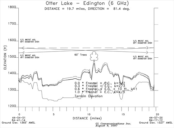
Typical Microwave Path Profile
IM Analyzer Tool (Free Limited Use)
Our IM tool analyzes intermodulation effects as part of the design process, and as site additions and expansions occur. Our customers in public transportation and wireless industry have greatly benefited from the tool and have insured reliability and voice intelligibility for their radio communications systems. Use of IM tool has helped engineers in identifying interference issues during the design phase. Through proper selection of transmit and receive frequencies, use of filters, and other appropriate design changes, we were able to help our customers avoid interference in the microwave/SMR networks. An example of our analysis is at Intermod Calculator.
GL offers these design tools Free to our customers for preliminary system design before they commit to major development costs. Two of the most important tools, IM Analyzer and Microwave Path Profile, are already available Online. Initially, the customers can input the data. GL will analyze the data and provide the results to the customers. We plan to make these tools fully available online in the future to enable you to design the network yourself. We plan to make available other tools, such as RF Propagation Prediction, Erlang Calculator and Terrain Map Viewer, free online in the near future.
In addition to the above tools, GL has developed, in house, an extensive array of advanced wireless system design tools. They include Geographic Plotting of GPS based data for Drive Testing and Evaluations, Microwave Inter-Connect, Erlang Calculator, RF Coverage, 2D and 3D Terrain Maps, Service Area Boundary Contours Study, TV station Grade-B contour interference analysis, Adjacent and Co-channels interference analysis, Carrier-to-Interferer Ratio Plots. You can contact us to obtain additional information.
We hope that you will continue to enjoy reading GL's newsletters. Future issues will highlight GL's support for projects such as:
- RF Propagation Prediction Tool
- Erlang Calculator for Trunked System
- WiMAX and WiFi technologies
- HVAC and Environmental Control of Outdoor Equipment Cabinets
- Metro Fire Security Management System
- Agency- wide Customer Information System for a Transit Network
 Back to Consulting Services Newsletters Page